Combined tube, combined tube assembly and evaporating and cooling equipment

A combined tube and cooling water technology, applied in lighting and heating equipment, machines using refrigerant evaporation, refrigerators, etc., can solve the problems of uneven distribution of water film, low cooling efficiency, large water consumption, etc., to save electricity and water consumption, the effect of improving efficiency

Pending Publication Date: 2017-12-22
成都歆雅春风科技有限公司
View PDF7 Cites 0 Cited by
  • Summary
  • Abstract
  • Description
  • Claims
  • Application Information

AI Technical Summary

Problems solved by technology

[0003] The evaporative cooling devices currently on the market are cooled fluid and cooling water in different pipes, resulting in uncontrollable evaporative cooling water film thickness, uneven distribution of water film, low cooling efficiency, and large water consumption.

Method used


Image

  • Combined tube, combined tube assembly and evaporating and cooling equipment
  • Combined tube, combined tube assembly and evaporating and cooling equipment
  • Combined tube, combined tube assembly and evaporating and cooling equipment

Examples


Embodiment 1

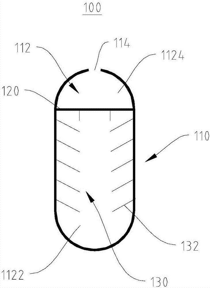
[0032] see figure 1 , this embodiment provides a combined pipe 100, the combined pipe 100 provided in this embodiment improves the utilization rate of the combined pipe 100 and saves space.

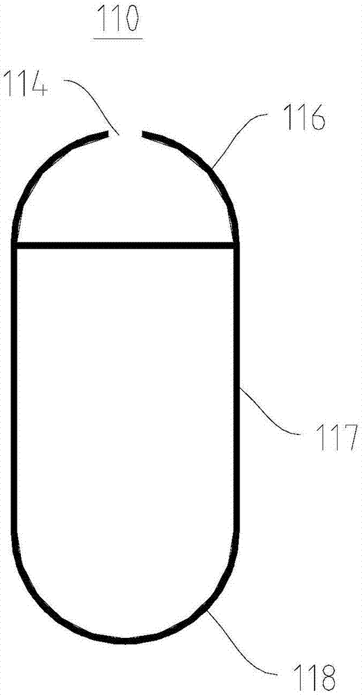
[0033] In this embodiment, the combined tube 100 includes a tube body 110, a partition 120, and a heat dissipation assembly 130. The tube body 110 has an accommodating cavity 112, and the partition 120 divides the accommodating cavity 112 into a first sub-accommodating cavity 1122 and a second sub-accommodating cavity 1122. Two sub-accommodating chambers 1124, the first sub-accommodating chamber 1122 is used to accommodate the cooled fluid, the second sub-accommodating chamber 1124 is used to accommodate cooling water, and the connecting pipe connects the second of two adjacent combined pipes 100. The sub-accommodating cavity 1124 . The heat dissipation assembly 130 is disposed in the first sub-accommodating chamber 1122 and connected to the inner sidewall of the tube body 110 .

[0034...

Embodiment 2

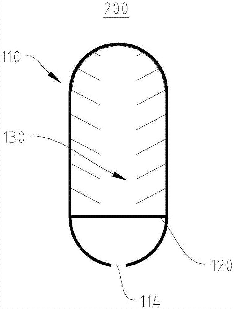
[0048] see image 3 , the combined pipe 200 provided in this embodiment, the combined pipe 200 provided in this embodiment improves the utilization rate of the combined pipe 200 and saves space.

[0049] The combined pipe 200 provided in this embodiment has the same basic structure and principle as well as the technical effects produced in the first embodiment. For brief description, for parts not mentioned in this embodiment, reference may be made to the corresponding content in the first embodiment.

[0050] The difference between the combination tube 200 provided in this embodiment and the first embodiment is that in this embodiment, the heat dissipation ribs 132 are arranged in a direction close to the partition plate 120 .

[0051] In this embodiment, when the combined pipe 200 is in working condition, the first sub-accommodation chamber 1122 is located above the second sub-accommodation chamber 1124 , and when the cooling water in the pipe body 110 flows from the second ...

Embodiment 3

[0053] see Figure 4 , the combined pipe assembly 10 provided in this embodiment, the combined pipe assembly 10 provided in this embodiment improves the utilization rate of the combined pipe assembly 10 and saves space.

[0054] For a brief description, reference may be made to Embodiment 1 and Embodiment 2 for the parts not mentioned in this embodiment.

[0055] In this embodiment, the combined tube assembly 10 includes a plurality of connecting tubes 300 and a plurality of combined tubes 100 , and the connecting tubes 300 connect two adjacent combined tubes 200 .

[0056] It should be noted that the combined tube assembly 10 may include the combined tube 100 in the first embodiment, or the combined tube 200 in the second embodiment. This embodiment takes the combined tube 100 in the first embodiment as an example for specific description.

[0057] In this embodiment, the connecting pipe 300 communicates with the second sub-accommodating chambers 1124 of two adjacent combina...


PUM


Abstract

The invention provides a combined tube, a combined tube assembly and evaporating and cooling equipment and relates to the field of electric equipment. The combined tube comprises a tube body and a partition plate. The tube body is provided with an accommodating cavity. The partition plate divides the accommodating cavity into a first sub accommodating cavity and a second sub accommodating cavity. The first sub accommodating cavity is used for accommodating a cooled fluid and the second sub accommodating cavity is used for accommodating cooling water. According to combined tube provided by the invention, the cooling water and the cooled fluid can be accommodated in the tube body at the same time, so that a water film on the surface of an evaporating and cooling pipeline is more uniform and thinner, and the evaporating and cooling efficiency is increased.

Description

technical field [0001] The invention relates to the field of home appliances, in particular to a combined pipe, combined pipe assembly and evaporative cooling equipment. Background technique [0002] There are currently three main types of condensers used in industrial applications or refrigeration equipment: air-cooled (forced convection), water-cooled and evaporative condensers. Evaporative condensers are widely used to enhance heat transfer and improve the performance of cooling systems, and improve the energy efficiency ratio of refrigeration systems (lowest condensation temperature, higher energy efficiency of refrigeration equipment). [0003] The evaporative cooling devices currently on the market are cooled fluid and cooling water in different pipes, resulting in uncontrollable evaporative cooling water film thickness, uneven water film distribution, low cooling efficiency, and high water consumption. Contents of the invention [0004] The purpose of the present i...

Claims


Application Information

Patent Timeline
Patent Type & Authority Applications(China)
IPC IPC(8): F25B19/00
CPCF25B19/00
Inventor 辜东海
Owner 成都歆雅春风科技有限公司
Why Eureka
Try Eureka