
Backlight and display device

A backlight and backplane technology, applied in light guides, optics, optical components, etc., can solve problems such as the inability to meet the narrow frame design requirements of mobile phones, and achieve the effects of improving picture quality, eliminating bright lines, and alleviating light concentration

Active Publication Date: 2017-12-22
BOE TECH GRP CO LTD +1
View PDF5 Cites 6 Cited by
  • Summary
  • Abstract
  • Description
  • Claims
  • Application Information

AI Technical Summary

Problems solved by technology

[0004] 1. Unable to meet the design requirements of the narrow frame of the mobile phone;

Method used


Image

  • Backlight and display device
  • Backlight and display device
  • Backlight and display device

Examples


Embodiment Construction

[0027] The following will clearly and completely describe the technical solutions in the embodiments of the present invention with reference to the accompanying drawings in the embodiments of the present invention. Obviously, the described embodiments are only some, not all, embodiments of the present invention. Based on the embodiments of the present invention, all other embodiments obtained by persons of ordinary skill in the art without making creative efforts belong to the protection scope of the present invention.

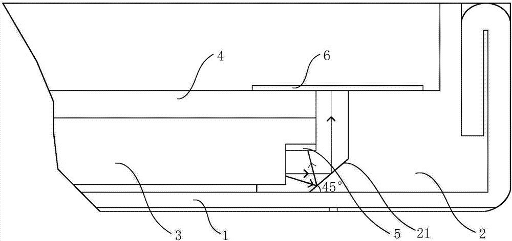
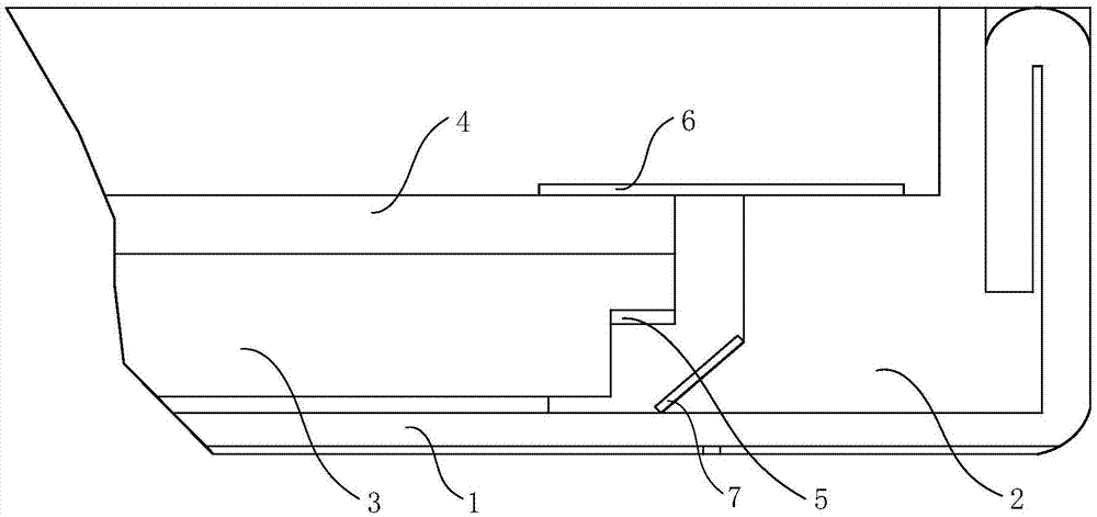
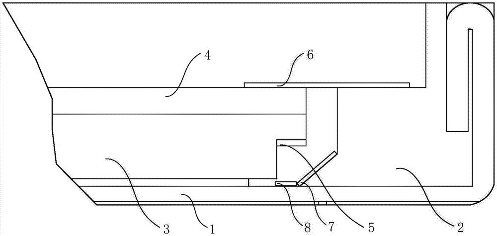
[0028] Please refer to figure 1 The present invention provides a backlight source, comprising a backplane 1, a plastic frame 2 installed on the backplane 1, a light guide plate 3 located in the accommodation space surrounded by the plastic frame 2, and a light guide plate 3 located on a side away from the backplane 1 and The optical film material 4 stacked with the light guide plate 3, at least one of the sides of the light guide plate 3 forms a light incident...


PUM


Abstract

The invention relates to the technical field of display and discloses a backlight and a display device. The backlight includes a backplane, a plastic frame mounted on the backplane, a light guide plate located in a receiving space enclosed by the plastic frame, and an optical film located at a position facing away from the light guide plate and overlapped with the light guide plate. At least one of the side surfaces of the light guide plate forms a light incident surface and the remaining side surfaces are non-light incident surfaces, wherein at least one of the non-light incident surface and the plastic frame match to form a light extinction structure to eliminate at leat a part of light from the non-light incident surfaces. The backlight provided by the present invention can eliminate the light emitted from the non-light-emitting surface of the light guide plate to a certain degree by the light extinction structure, and can eliminate the weakening or even bright lines and improve the picture quality of the backlight well.

Description

technical field [0001] The invention relates to the field of display technology, in particular to a backlight source and a display device. Background technique [0002] The backlight is a light source located behind the liquid crystal display. In the side-emitting backlight structure, bright lines are generally produced on the light-emitting side. The reason for the bright line is that the light emitted from the non-light-incident surface of the light guide plate is reflected by the plastic frame, and after being reflected back to the light guide plate, it overlaps with the light inside the light guide plate, resulting in concentrated light, and then scatters to the light guide plate through the dots of the light guide plate. The light-emitting surface of the light panel increases the amount of light emitted per unit area, resulting in a significant increase in the brightness of a local area, creating a visually bright effect for the human eye, thereby forming a bright line ...

Claims


Application Information

Patent Timeline
Patent Type & Authority Applications(China)
IPC IPC(8): G02B6/00G02F1/13357G02F1/1335
CPCG02B6/0088G02F1/133512G02F1/133608G02F2201/08G02B6/0065G02B6/0035G02B6/0015G02B5/003G02F1/133334G02B6/0016G02B6/0055
Inventor 刘彦军邓立广翟明刘宇飞姚金明
Owner BOE TECH GRP CO LTD
Learn More