
Display panel and display device

A technology of display panel and display area, which is applied to instruments, computing, electrical and digital data processing, etc., can solve the problems of jagged edges of the display screen, insufficient setting of pixels, poor overall image quality, etc., to avoid edge color mixing and color cast, Avoid jagged edges, high aperture effects

Active Publication Date: 2017-12-22
WUHAN TIANMA MICRO ELECTRONICS CO LTD
View PDF7 Cites 6 Cited by
  • Summary
  • Abstract
  • Description
  • Claims
  • Application Information

AI Technical Summary

Problems solved by technology

[0003] figure 1 It is a schematic structural diagram of a non-rectangular display device in the prior art; figure 1 As shown, when the display area boundary S of the display device is an arc boundary, since the area of ​​the display area A close to the arc boundary is small, it is not enough to set a complete pixel. Therefore, the existing non-rectangular display device displays Generally, no pixels are set in area A, that is, neither the array substrate nor the color filter substrate has settings corresponding to the pixel structure in this area; however, the lack of pixels in this display area will lead to the lack of display information and will cause the display screen to appear More noticeable jagged edges, resulting in poorer overall image quality

Method used


Image

  • Display panel and display device
  • Display panel and display device
  • Display panel and display device

Examples


Embodiment approach

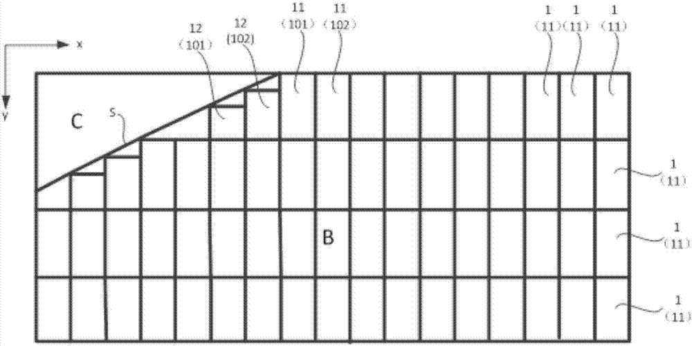
[0049] Method 1, such as figure 2 As shown, the sub-pixels include yellow sub-pixels 101 and blue sub-pixels 102. The yellow sub-pixels 101 and blue sub-pixels 102 are arranged alternately in the row direction x of the sub-pixel array. A pair of adjacent yellow sub-pixels 101 and blue sub-pixel 102 form a pixel unit.

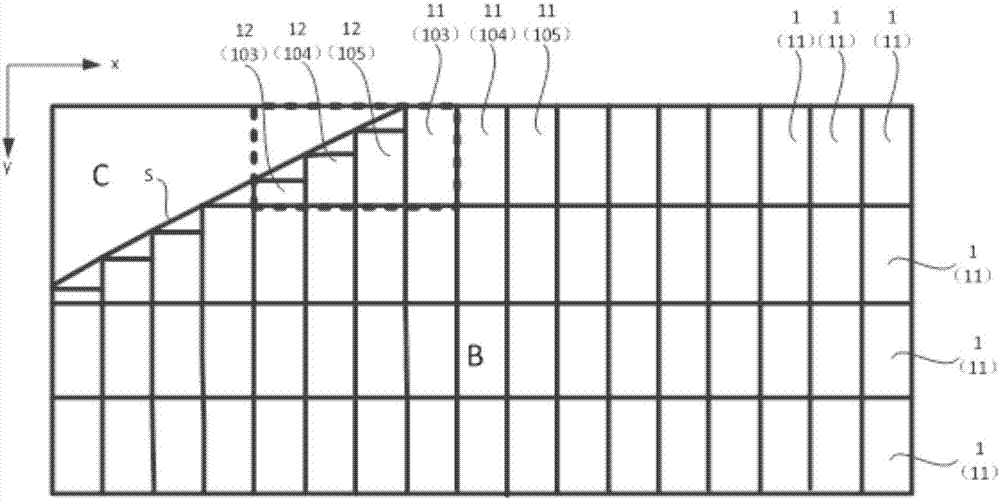
[0050] Furthermore, in the display panel provided by this embodiment, edge yellow sub-pixels 101 and edge blue sub-pixels 102 are arranged near the boundary S of the display area, so that the continuity of the display information of the display panel is very good, and the display of the display panel The edge boundary is smooth and does not present a jagged edge; in addition, along the row direction x of the sub-pixel array, between the adjacent edge yellow sub-pixel 101 and the edge blue sub-pixel 102, and between the edge blue sub-pixel 102 and the edge blue sub-pixel 102 Shading strips are provided between the adjacent internal yellow sub-pixels 101 , so th...

specific Embodiment approach

[0061] Method 1, such as Figure 5 As shown, the light-shielding strip 2 only includes a first portion 21 extending along the edge of the opening of the second sub-pixel 14; that is, the light-shielding strip 2 is only arranged in an area where there is a risk of color mixing and color shift between two sub-pixels; the first sub-pixel 13 A section of the area where the opening part exceeds the opening part of the second sub-pixel 14 has no risk of color mixing and color shift, therefore, no light-shielding structure is provided in this area. Furthermore, in the display panel provided by this embodiment, when there is an alignment deviation between the array substrate and the color filter substrate during the alignment process, the setting of the light-shielding strip 2 can minimize the influence on the pixel aperture ratio; specifically , for example, as Figure 7 As shown, when there is an alignment deviation between the color filter substrate and the array substrate along t...


PUM


Abstract

The invention relates to the technical field of displaying, and discloses a display panel and a display device. The display panel is provided with a non-rectangular display area and a non-display area which surrounds the display area; the display panel comprises subsidiary pixels which are distributed in an array mode, and adjacent subsidiary pixels form pixel units in the line direction of the array; the subsidiary pixels comprise internal subsidiary pixels which are totally located in the display area and edge subsidiary pixels which are arranged along the edges of the display area and of which the aperture is smaller than that of the internal subsidiary pixels; light-shading strips are arranged between each edge subsidiary pixel and the corresponding subsidiary pixel adjacent to the edge subsidiary pixel in the line direction, and extend in the line direction of the array. The display panel can improve the continuity of the non-rectangular display panel of displaying information and the gentleness of the display edge limit, and the occurrence of edge color mixing and color deviation can be avoided.

Description

technical field [0001] The present invention relates to the field of display technology, in particular to a display panel and a display device. Background technique [0002] As the smart terminal products become more and more abundant, the shapes of the display devices of the smart terminals are also more abundant, and furthermore, non-rectangular display devices are very common now. [0003] figure 1 It is a schematic structural diagram of a non-rectangular display device in the prior art; figure 1 As shown, when the display area boundary S of the display device is an arc-shaped boundary, since the area of ​​the display area A close to the arc-shaped boundary is small, it is not enough to set a complete pixel. Therefore, the existing non-rectangular display device displays Pixels are generally not set in area A, that is, neither the array substrate nor the color filter substrate has settings corresponding to the pixel structure in this area; however, the lack of pixels in...

Claims


Application Information

Patent Timeline
Patent Type & Authority Applications(China)
IPC IPC(8): G02F1/1335G02F1/1333G06F3/041
CPCG02F1/1333G02F1/13338G02F1/133512G06F3/041
Inventor 凌安恺马扬昭吴玲沈柏平
Owner WUHAN TIANMA MICRO ELECTRONICS CO LTD
Learn More