
DSP remote debugging device and method based on serial communication

A technology of remote debugging and serial communication, which is applied in the direction of program control, general control system, electrical testing/monitoring, etc., and can solve the problem that remote debugging and data recording cannot be completed, program variable changes cannot be recorded, and debuggers cannot debug on site And other issues

Active Publication Date: 2017-12-22
INST OF OPTICS & ELECTRONICS - CHINESE ACAD OF SCI
View PDF3 Cites 7 Cited by
  • Summary
  • Abstract
  • Description
  • Claims
  • Application Information

AI Technical Summary

Problems solved by technology

Because of the USB transmission distance, the target board cannot be too far away from the debugging computer, and the variables in the program can only be observed through breakpoints in the integrated development environment, and it is impossible to record the variable changes during the actual operation of the program. In mines, nuclear power plants, etc., The location of the target board is limited by the environment, and debuggers cannot debug on site, but can only debug remotely. The remote debugging and data recording cannot be completed through the debugging method of the USB dedicated emulator. It is necessary to study the limitations of general, out of emulator and specific debugging protocols. remote DSP debugging method

Method used


Image

  • DSP remote debugging device and method based on serial communication
  • DSP remote debugging device and method based on serial communication
  • DSP remote debugging device and method based on serial communication

Examples


Embodiment Construction

[0055] The present invention will be further described below in conjunction with the accompanying drawings and specific embodiments.

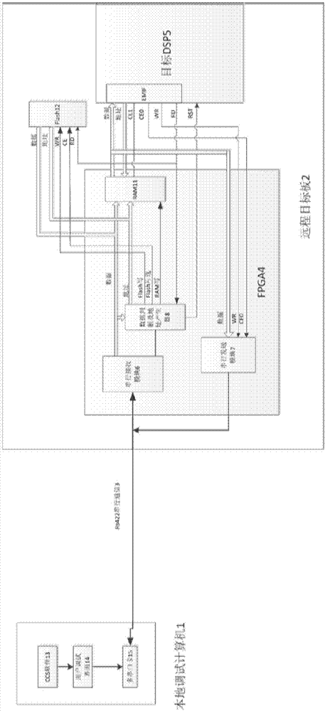
[0056] Such as figure 1 Shown, a kind of DSP debugging method based on serial communication of the present invention, hardware comprises: local debugging computer 1, remote target board 2, RS422 serial communication bus 3; Described remote target board 2 comprises FPGA 4, Flash program memory 12 and DSP 5; the internal logic of the FPGA 4 includes a serial receiving module 6, a serial sending module 7, a data judgment and address generating module 8, and a program storage dual-port RAM11. The local debugging computer 1 includes a software integrated development environment CCS13, a multi-serial port card 15 and a user debugging interface 14. The multi-serial port card 15 is connected with the remote target board 2 through the RS422 serial communication bus 3 to complete two-way RS422 communication. The local debugging computer 1 includes an i...


PUM


Abstract

The invention discloses a DSP remote debugging device and method based on serial communication. The method is characterized by realizing source program compiling and linking in a local computer to generate a target file; sending the target file to a remote target board FPGA through a two-way RS422 serial communication bus; during debugging, simulating a Flash function through the FPGA; after the FPGA receives the target file, resetting a DSP; through the DSP, reading program data from the FPGA and operating the data, and exchanging observation variable storage address through the FPGA, so that required observation variables can be checked and recorded in the local computer; and after DSP debugging, writing the target file into Flash through the FPGA to finish the program curing work. The device and method are suitable for occasions of mines and nuclear power stations and the like, where remote debugging and program remote loading are needed, and meanwhile, are suitable for occasion of a large-scale rotary table and the like, where breakpoint debugging cannot be used; and through RS422 serial transmission, distance can reach thousands of meters.

Description

technical field [0001] The invention belongs to the field of computer control, in particular to a DSP remote debugging device and method based on serial communication. Background technique [0002] Digital Signal Processor DSP (Digital Signal Processor) has powerful processing and computing capabilities, and is widely used in image processing, radar signal processing, industrial control and other fields. At present, DSP software developers mostly rely on special USB emulators for debugging. Debugging in the integrated development environment provided by the manufacturer uses the manufacturer's special JTAG debugging protocol, which is not open to users. Because of the USB transmission distance, the target board cannot be too far away from the debugging computer, and the variables in the program can only be observed through breakpoints in the integrated development environment, and it is impossible to record the variable changes during the actual operation of the program. In ...

Claims


Application Information

Patent Timeline
Patent Type & Authority Applications(China)
IPC IPC(8): G05B23/02
CPCG05B23/0213G05B2219/24065
Inventor 杜升平徐少雄刘琼郭弘扬
Owner INST OF OPTICS & ELECTRONICS - CHINESE ACAD OF SCI
Learn More