Digital power control method, device and system

A technology of digital power supply and control device, applied in the direction of output power conversion device, electrical components, etc., can solve the problems of reducing debugging efficiency, reducing product quality control, increasing the complexity and workload of power supply design, and improving portability. and efficiency, improve the efficiency of debugging, and realize the effect of remote debugging

Inactive Publication Date: 2017-11-10
BEIJING INST OF RADIO MEASUREMENT
View PDF5 Cites 0 Cited by
  • Summary
  • Abstract
  • Description
  • Claims
  • Application Information

AI Technical Summary

Problems solved by technology

[0003] At present, the analog control technology of switching power supply is very mature, and the market share of analog control chips is also very high, but analog control chips generally only correspond to one control mode, and the redesign of the main circuit often requires the redesign of the control circuit, increasing Reduced the complexity and workload of power supply design
[0004] At the same time, during the debugging process of switching power supply, it is necessary to constantly modify parameters such as PWM cycle, dead zone, and PID. Analog control can only realize the modification of parameters by modifying the corresponding hardware such as capacitors and resistors. It is inconvenient and reduces the debugging efficiency. On the one hand, it also reduces the control of product quality. Moreover, the current power switch debugging device is bulky and inconvenient to carry.

Method used


Image

  • Digital power control method, device and system
  • Digital power control method, device and system
  • Digital power control method, device and system

Examples


Embodiment Construction

[0041] The principles and features of the present invention are described below in conjunction with the accompanying drawings, and the examples given are only used to explain the present invention, and are not intended to limit the scope of the present invention.

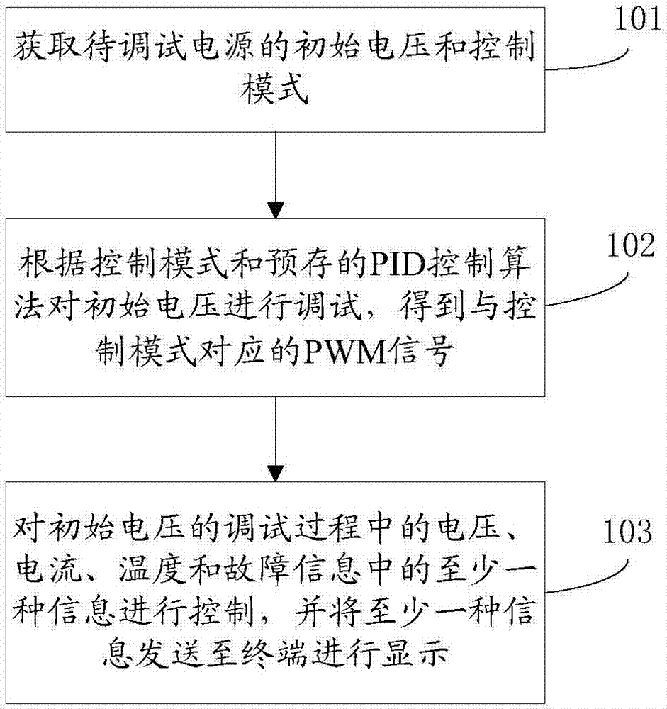
[0042] Such as figure 1 As shown, it is a schematic flowchart of a digital power supply control method provided by an embodiment of the present invention, and the control method mainly includes the following steps.

[0043] S101. Obtain the initial voltage and control mode of the power supply to be debugged. For example, the power supply to be debugged here may be a radar power supply.

[0044] S102, debug the initial voltage according to the control mode and the pre-stored PID control algorithm, and obtain a PWM signal corresponding to the control mode.

[0045] S103. Control at least one information among voltage, current, temperature and fault information during initial voltage debugging, and send at least one i...


PUM


Abstract

The invention relates to a digital power control method, device and system. The method comprises the following steps of acquiring an initial voltage and a control mode of a to-be-debugged power; debugging the initial voltage according to the control mode and a pre-stored PID control algorithm, so as to obtain a PWM signal corresponding to the control mode; and controlling at least one of voltage, current, temperature and failure information in the debugging process of the initial voltage, and sending the at least one information to a terminal to display. Through adoption of the digital power control method, device and system, the debugging efficiency is improved, the design workload and design complexity of a control circuit of a switch power are lowered, the power can be debugged in a long distance, and the power can be debugged more portably and efficiently.

Description

technical field [0001] The present invention relates to the field of power supply control, in particular to a digital power supply control method, device and system. Background technique [0002] With the development of power supply technology, the radar power supply has changed from a very bulky linear power supply to a switching power supply commonly used today. [0003] At present, the analog control technology of switching power supply is very mature, and the market share of analog control chips is also very high, but analog control chips generally only correspond to one control mode, and the redesign of the main circuit often requires the redesign of the control circuit, increasing The complexity and workload of power supply design are reduced. [0004] At the same time, during the debugging process of switching power supply, it is necessary to constantly modify parameters such as PWM cycle, dead zone, and PID. Analog control can only realize the modification of parame...

Claims


Application Information

Patent Timeline
Patent Type & Authority Applications(China)
IPC IPC(8): H02M1/00
CPCH02M1/00H02M1/0012
Inventor 冉崇建黎明苟伟
Owner BEIJING INST OF RADIO MEASUREMENT
Why Eureka
Try Eureka