Switch cabinet dehumidification system

A technology for switch cabinets and access switches, which is applied to substation/switch layout details, electrical components, substation/power distribution device shells, etc., which can solve the impact on the safe operation of switch cabinets, hidden safety hazards in switch cabinet operation, and cost a lot of manpower and material resources, etc. problem, to achieve the effect of ensuring safe operation and working stability, simple dehumidification method and good dehumidification effect

Inactive Publication Date: 2017-12-22
ZHEJIANG BAIYUNYUAN ELECTRIC +2
View PDF2 Cites 2 Cited by
  • Summary
  • Abstract
  • Description
  • Claims
  • Application Information

AI Technical Summary

Problems solved by technology

Although the use of refrigerated dehumidifiers can reduce the moisture content of the air in the cabinet, there are many problems, the most prominent is the inconvenience of maintenance
[0004] At present, there are a large number of refrigerated dehumidifiers that have failed. Since they are installed in the switch cabinet, they need to apply to the relevant departments for maintenance.
Therefore, it is generally chosen to carry out maintenance when the switchgear is overhauled, but the interval between switchgear maintenance is very long, and there are potential safety hazards in the operation of the switchgear without a dehumidifier
In addition, installing the dehumidifier in the switch cabinet is also a time-consuming and laborious task; the dehumidifier directly discharges water into the cable trench, and the moisture is not completely removed, and it will still enter the switch through the gap in the switch cabinet; the dehumidifier needs to be removed from the switch cabinet. Electricity, which affects the safe operation of the switchgear

Method used


Image

  • Switch cabinet dehumidification system
  • Switch cabinet dehumidification system
  • Switch cabinet dehumidification system

Examples


Embodiment 1

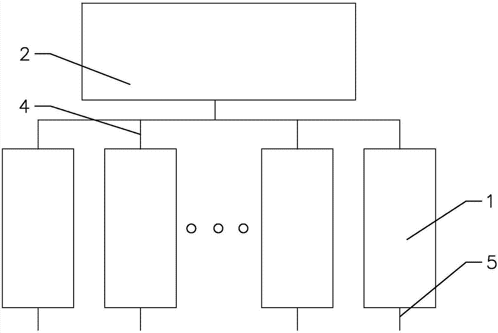
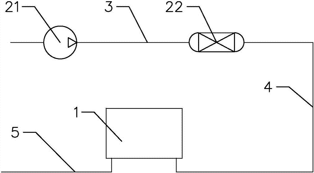
[0042] Such as figure 1 , 2 As shown, the present invention provides a switchgear dehumidification system, including multiple sets of switchgears 1 and switchgear dehumidifiers 2 connected to multiple sets of switchgears, the switchgear dehumidifiers 2 are located outside the switchgear 1, because the existing switchgear The cabinet dehumidification device is installed inside the switch cabinet. When the switch cabinet dehumidification device fails, the switch cabinet needs to be powered off before the switch cabinet dehumidification device can be repaired, which brings a lot of inconvenience and economic loss to the user. By dehumidifying the switch cabinet The device is installed outside the switch cabinet. When the dehumidification device of the switch cabinet fails, it is not necessary to turn on the switch cabinet after power failure, and then repair the dehumidification device of the switch cabinet. The dehumidification device of the switch cabinet can be repaired direct...

Embodiment 2

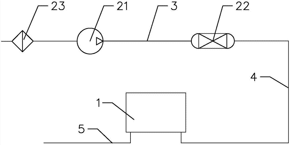
[0048] The difference between this embodiment and the first embodiment is that the air supply unit further includes an air filter.

[0049] In this example, if image 3 As shown, the air supply unit also includes an air filter 23 communicated with the air inlet of the air compressor 21, and the external air enters the air compressor 21 through the air filter 23, so that when the external air enters the air compressor, it is first The air filter is used to filter out dust and impurities in the external air, so as to prevent dust, impurities and other substances from clogging air ducts, air compressors and other components, and to better prevent dust and impurities from entering the switch cabinet and causing damage. The components in the switch cabinet are damaged or out of order to ensure the safe operation and normal operation of the switch cabinet.

[0050] Other structures and beneficial effects not described are the same as those in Embodiment 1.

Embodiment 3

[0052] The difference between this embodiment and the first embodiment is that the air supply unit further includes an air storage tank.

[0053] In this example, if Figure 4 As shown, the air supply unit also includes an air storage tank 24 communicated with the air outlet of the air compressor 21, the air storage tank 24 is provided with a pressure switch 241, the pressure switch 241 is located inside the air storage tank 24, and the air storage tank 24 There is a drain valve 242 at the bottom of the tank. Since the air compressor condenses part of the compressed moisture into water, it can be discharged from the drain valve 242, and the air storage tank 24 can pressurize the air to ensure the power of the air in the subsequent delivery process. , so as to ensure a good dehumidification effect, and set a pressure switch on the air storage tank. When the pressure in the air storage tank exceeds the preset value, the power supply of the air compressor will be automatically di...


PUM


Abstract

The invention provides a switch cabinet dehumidification system, which comprises multiple groups of switch cabinets and a switch cabinet dehumidification device which is connected with the multiple groups of switch cabinets, wherein the switch cabinet dehumidification device is arranged outside the switch cabinets; the switch cabinet dehumidification device comprises an air supply unit communicated with the outside air, a drying unit, air guide pipes which connect the air supply unit and the drying unit, air inlet pipes and air outlet pipes; the air inlet pipes and the air outlet pipes are communicated with the switch cabinet separately; the air supply unit provides air; and the air is dried by means of the drying unit, then enters the switch cabinets by means of the air inlet pipes and exhaust humid air in the switch cabinets by means of the air outlet pipes. By arranging the switch cabinet dehumidification device outside the switch cabinets, the power supply does not need to be cut off and the switch cabinets do not need to be opened so as to maintain the switch cabinet dehumidification device when the switch cabinet dehumidification device fails, and the switch cabinet dehumidification device can be maintained directly outside the switch cabinets, thereby the maintenance of the switch cabinet dehumidification device is facilitated, and inconveniences and economic losses to users due to power-off maintenance cannot be brought.

Description

technical field [0001] The invention relates to the technical field of power transmission and distribution and control, in particular to a switch cabinet dehumidification system. Background technique [0002] The humidity in the switchgear has an important impact on the electrical safety in the switchgear and the life of the cable terminal, so it is necessary to reasonably control the humidity in the switchgear. There are two main types of dehumidification devices currently used for switchgear dehumidification: one is a heating plate, and the other is a refrigerated dehumidifier. [0003] The refrigerated dehumidifier is the most widely used method at present. Its principle is to install the refrigerated dehumidifier in the switch cabinet, use the fan to suck the air in the cabinet into the dehumidifier, and when the air passes through the condensation device inside the dehumidifier, The moisture liquefies into water droplets and stays in the dehumidifier, and the dried air...

Claims


Application Information

Patent Timeline
Patent Type & Authority Applications(China)
IPC IPC(8): H02B1/28H02B1/32
CPCH02B1/28H02B1/32
Inventor 雷超许晓伟郑建军方明俊徐鹏建皇甫伟钢许小平肖高远徐榕拥程铖俞凯庞昭华王腾飞陈彦哲洪杰邓文辉陈涛李周青陶志刚
Owner ZHEJIANG BAIYUNYUAN ELECTRIC
Why Eureka
Try Eureka