Motor rotor

A technology of motor rotor and rotor iron core, applied in electrical components, electromechanical devices, electric components, etc., can solve the problem of small contact surface between permanent magnet and rotor iron core, difficulty in matching between magnetic steel and rotor iron core, affecting motor stability and Safety and other issues, to achieve the effect of saving labor costs, low costs, and easy control

Pending Publication Date: 2017-12-22
TIANJIN KANGTU TECH CO LTD
View PDF4 Cites 4 Cited by
  • Summary
  • Abstract
  • Description
  • Claims
  • Application Information

AI Technical Summary

Problems solved by technology

The chute is the main method used by the motor at present, but the chute will cause difficulty in winding the winding and increase the cost of the motor
[0004] In terms of oblique poles, due to the widespread use of tile-shaped magnets, it is difficult to match the magnets with the rotor core, and the assembly accuracy is difficult to guarantee.
Using the inclined pole method, the contact surface between the permanent magnet and the rotor core will be very small, and it will be difficult to fix it. If it is not handled properly, it will directly affect the stability and safety of the motor.
In addition, due to the processing method, the price of tile-shaped magnets commonly used at present is higher than that of square magnets, and the processing accuracy of tile-shaped magnets is also lower than that of square magnets.

Method used


Image

  • Motor rotor
  • Motor rotor
  • Motor rotor

Examples


Embodiment 1

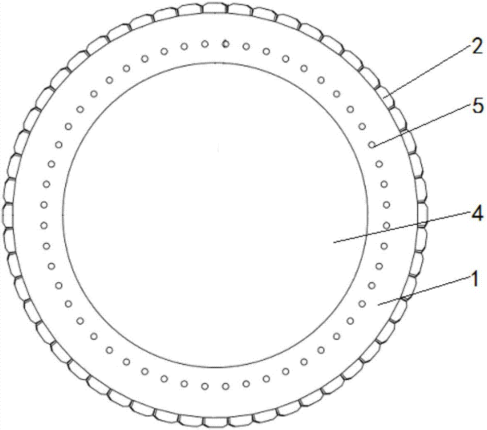
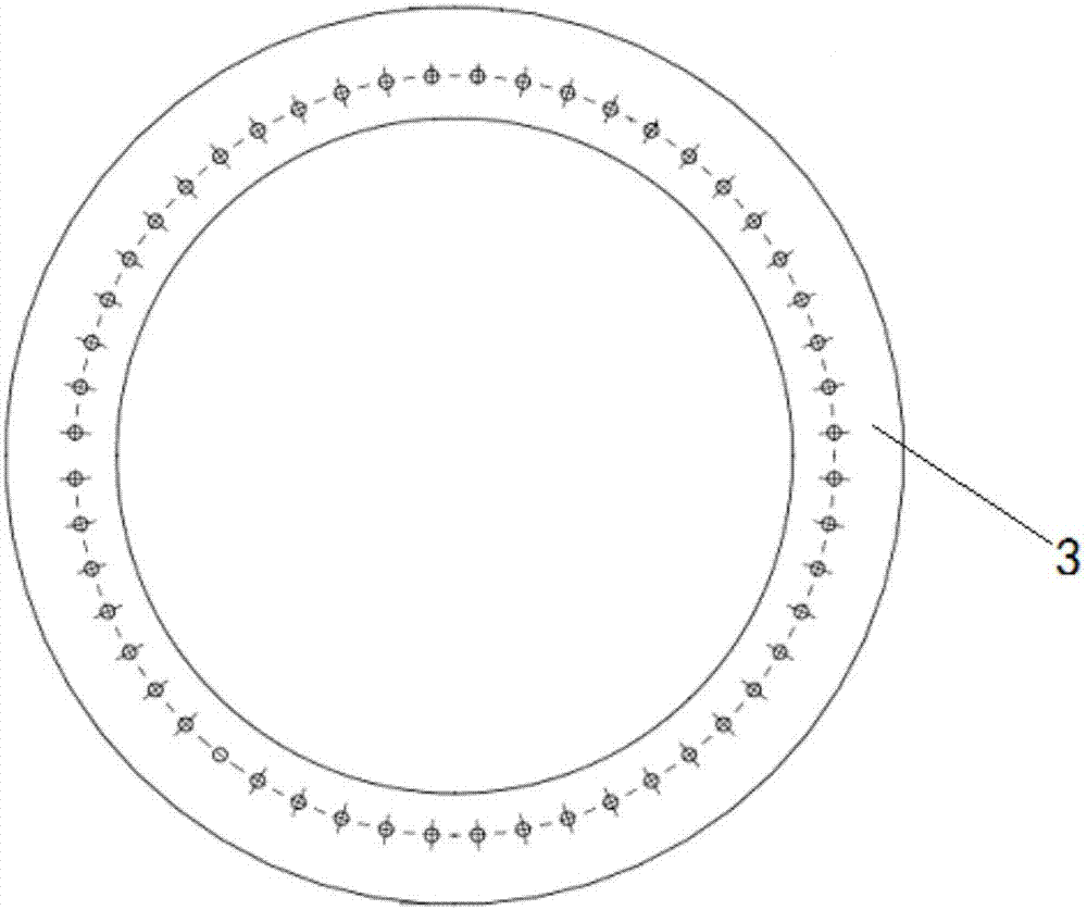
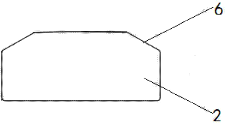
[0027] Such as Figure 1-3 The shown motor rotor includes a rotor core 1 and permanent magnets, and the permanent magnets are adhered to the surface of the rotor core 1 . The rotor core 1 is formed by stacking the rotor punches 3, and the surface of the rotor core 1 and the permanent magnet 2 is a regular polygon, so that the permanent magnet 2 has an inclination angle, and then the rotor core 1 is connected to the rotor core. 1 Pasting, the process is simple and saves labor costs, and the accuracy of the inclination angle is relatively easy to control, which ensures the performance of the motor. In addition, the number of sides is equal to the number of stages 2P designed by the motor, and a round hole 4 is opened in the middle of the rotor core 1, and the round hole 4 is matched with the motor shaft. Positioning holes 5 are evenly distributed along the circumference of the rotor core 1, and the number of the positioning holes 5 is also equal to the number of stages 2P desig...

Embodiment 2

[0031] Such as figure 1 , 2 A motor rotor shown in and 4 includes a rotor core 1 and permanent magnets, and the permanent magnets are adhered to the surface of the rotor core 1 . The rotor core 1 is formed by stacking the rotor punches 3, and the surface of the rotor core 1 and the permanent magnet 2 is a regular polygon, so that the permanent magnet 2 has an inclination angle, and then the rotor core 1 is connected to the rotor core. 1 Pasting, the process is simple and saves labor costs, and the accuracy of the inclination angle is relatively easy to control, which ensures the performance of the motor. In addition, the number of sides is equal to the number of stages 2P designed by the motor, and a round hole 4 is opened in the middle of the rotor core 1, and the round hole 4 is matched with the motor shaft. Positioning holes 5 are evenly distributed along the circumference of the rotor core 1, and the number of the positioning holes 5 is also equal to the number of stages...

Embodiment 3

[0035] Such as figure 1 , 2 A motor rotor shown in , 3 and 5 includes a rotor core 1 and a permanent magnet, and the permanent magnet is adhered to the surface of the rotor core 1 . The rotor core 1 is formed by stacking the rotor punches 3, and the surface of the rotor core 1 and the permanent magnet 2 is a regular polygon, so that the permanent magnet 2 has an inclination angle, and then the rotor core 1 is connected to the rotor core. 1 Pasting, the process is simple and saves labor costs, and the accuracy of the inclination angle is relatively easy to control, which ensures the performance of the motor. In addition, the number of sides is equal to the number of stages 2P designed by the motor, and a round hole 4 is opened in the middle of the rotor core 1, and the round hole 4 is matched with the motor shaft. Positioning holes 5 are evenly distributed along the circumference of the rotor core 1, and the number of the positioning holes 5 is also equal to the number of sta...


PUM


Abstract

The invention provides a motor rotor, which includes a rotor iron core and a permanent magnet. The permanent magnet is adhered to the surface of the rotor iron core. The rotor iron core is formed by lamination of rotor punching sheets. The side, adhered to the permanent magnet, of the rotor iron core is a regular polygon side, and the number of edges of the regular polygon equals the designed number 2P of magnetic poles of a motor. The center of the rotor iron core is equipped with a circular hole, and the circular hole matches a motor shaft. Positioning holes are evenly distributed in the circumference of the rotor iron core, and the number of the positioning holes also equals the designed number 2P of magnetic poles of a motor. The motor rotor is simple in process, and the labor cost is saved. In addition, the inclination angle precision is easy to control, and the use performance of a motor is guaranteed.

Description

technical field [0001] The invention belongs to the technical field of traction machine motor rotor equipment, and in particular relates to a motor rotor. Background technique [0002] Cogging torque is the torque generated by the interaction between the permanent magnet and the stator core when the winding of the permanent magnet motor is not energized, and is caused by the tangential component of the interaction force between the permanent magnet and the armature teeth. Cogging torque is one of the unique problems of permanent magnet motors, and it is a key issue that must be considered and solved in the design and manufacture of high-performance permanent magnet motors. [0003] The methods to weaken the cogging torque include: changing the pole arc coefficient of the magnetic pole, using unequal thickness permanent magnets, magnetic pole offset, oblique pole, magnetic pole segmentation, unequal pole arc coefficient combination, using unequal pole arc coefficient, changin...

Claims


Application Information

Patent Timeline
Patent Type & Authority Applications(China)
IPC IPC(8): H02K1/27
CPCH02K1/278
Inventor 冯延坤
Owner TIANJIN KANGTU TECH CO LTD
Why Eureka
Try Eureka