Braking force compensation method under air brake fault condition

A technology of air braking and compensation method, applied in the direction of brakes, etc., can solve the problems of train braking force loss, inability to open, hidden dangers, etc., and achieve the effect of eliminating hidden dangers, easy to implement, and strong applicability

Active Publication Date: 2017-12-26
CRRC QINGDAO SIFANG ROLLING STOCK RES INST
View PDF5 Cites 22 Cited by
  • Summary
  • Abstract
  • Description
  • Claims
  • Application Information

AI Technical Summary

Problems solved by technology

[0003] If the electric brake fails, the brake system can compensate the loss of electric brake force by applying air brake to ensure that the brake force of the train meets the braking demand, but when the brake system of one or more carriages fails and cannot apply air After braking, there is currently no clear compensation method for the braking force, which will cause the loss of the braking force of the train and increase the braking distance. The possible impacts are:
[0004] (1) When the train needs to be decelerated during operation, the train speed may exceed the speed limit due to insufficient braking force, posing a safety hazard, causing emergency braking triggered by the automatic protection system, causing the train to stop on the line, and affecting the operation of subsequent trains ;
[0005] (2) When the train stops at the station, due to insufficient braking force, the braking distance increases, which may cause the train to stop at the station or exceed the beacon. For a large number of stations with screen doors at present, if the parking accuracy is not enough , the doors and screen doors cannot be opened, and passengers cannot be loaded and unloaded, thus affecting the operation of the line;
[0006] (3) For trains that fail to apply air brake due to brake system failure, due to the problem caused by the loss of braking force, the faulty train can only run at a limited speed until the next station or the terminal station to clear passengers off the assembly line. operation has a great impact

Method used


Image

  • Braking force compensation method under air brake fault condition
  • Braking force compensation method under air brake fault condition
  • Braking force compensation method under air brake fault condition

Examples


Embodiment Construction

[0026] In the following, the present invention will be specifically described through exemplary embodiments. It should be understood, however, that elements, structures and characteristics of one embodiment may be beneficially incorporated in other embodiments without further recitation.

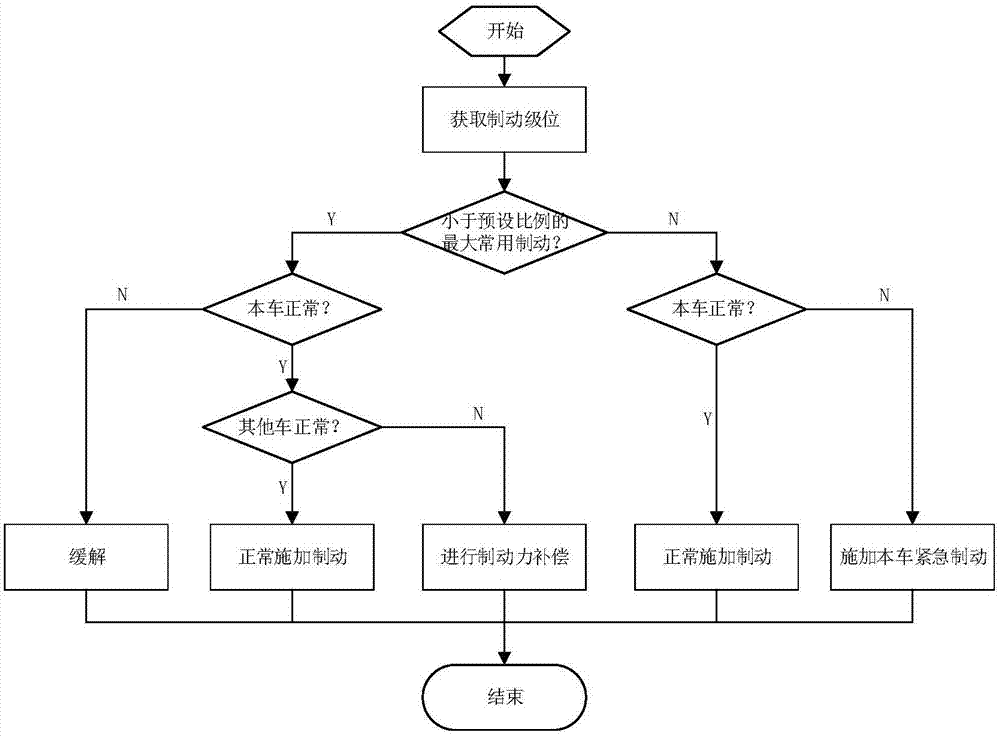
[0027] Such as figure 1 As shown, the present invention provides a braking force compensation method in the case of an air brake failure, which is used when the train braking system fails and the air brake cannot be applied. The braking force compensation method specifically includes: judging the braking level If the position is less than the maximum common braking force of the preset ratio, if so, the air brake of the faulty car will be relieved, and the other normal cars will compensate the braking force of the faulty car to compensate for the loss of the braking force of the faulty car; if not, the faulty car will apply its own braking force. Emergency braking to compensate for the loss ...


PUM


Abstract

The invention provides a braking force compensation method under an air brake fault condition. The braking force compensation method is used for judging whether or not the brake level is lower than the value of a largest common braking force of a preset proportion when a carriage brake system of a city rail train fails so that air brake cannot be applied, if yes, air brake in the failed carriage is alleviated, and the other normal carriages compensate the braking force loss of the failed carriage so that the braking force requirement of the whole train can be met; if no, the failed carriage applies emergency brake on the whole train to compensate the braking force loss so that the whole train can meet the brake requirement. The compensation method makes the braking force of the train meet the brake requirement, removes hidden safety hazards, and does not influence operation of a driver and line operation.

Description

technical field [0001] The invention belongs to the field of urban rail trains, in particular to a braking force compensation method for urban rail trains under the condition of air brake failure. Background technique [0002] At present, the braking force of most urban rail trains mainly comes from the electric braking force provided by the traction system and the air braking force provided by the braking system. The common braking and fast braking functions of the train all use electric-pneumatic hybrid braking. , the basic principle of electro-pneumatic hybrid braking is to use electric braking first, and when the electric braking force cannot meet the braking demand, it is supplemented by air braking. [0003] If the electric brake fails, the brake system can compensate the loss of electric brake force by applying air brake to ensure that the brake force of the train meets the braking demand, but when the brake system of one or more carriages fails and cannot apply air ...

Claims


Application Information

Patent Timeline
Patent Type & Authority Applications(China)
IPC IPC(8): B60T8/88B60T8/94B60T8/17
CPCB60T8/1705B60T8/885B60T8/94
Inventor 赵欣胡波孙全涛
Owner CRRC QINGDAO SIFANG ROLLING STOCK RES INST
Why Eureka
Try Eureka