
Battery testing fixture

A technology of battery testing and fixtures, which is applied to the components of electrical measuring instruments, measuring devices, and measuring electrical variables, etc., can solve the problems of irreversible damage to battery poles, low efficiency, etc., to ensure voltage acquisition accuracy, flexible application, and meet Effect of High Current Test Requirements

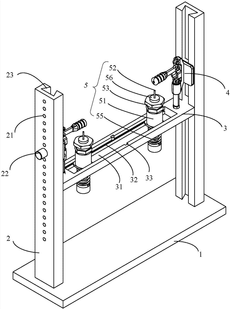
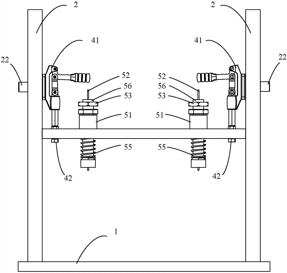
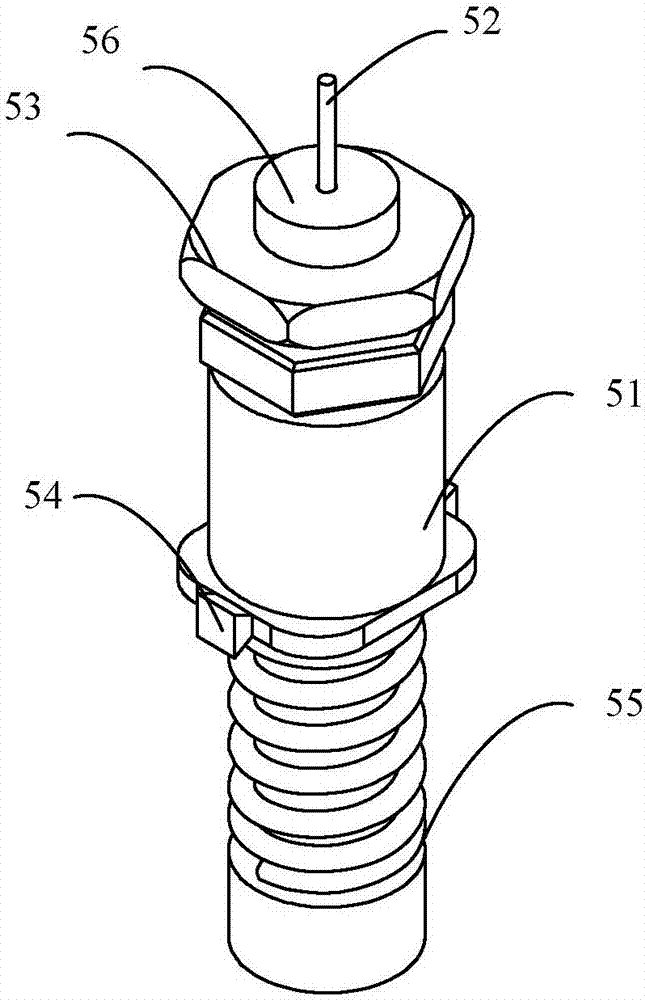
Pending Publication Date: 2017-12-26
BEIJING PRIDE NEW ENERGY BATTERY
View PDF10 Cites 3 Cited by
  • Summary
  • Abstract
  • Description
  • Claims
  • Application Information

AI Technical Summary

Problems solved by technology

However, there are irreversible damage to the battery pole and low efficiency

Method used


Image

  • Battery testing fixture
  • Battery testing fixture
  • Battery testing fixture

Examples


Embodiment Construction

[0025] In order to make the purpose, technical solutions and advantages of the embodiments of the present disclosure clearer, the technical solutions of the embodiments of the present disclosure will be clearly and completely described below in conjunction with the drawings of the embodiments of the present disclosure. Apparently, the described embodiments are some of the embodiments of the present disclosure, but not all of them. Based on the described embodiments of the present disclosure, all other embodiments obtained by persons of ordinary skill in the art without creative effort fall within the protection scope of the present disclosure.

[0026] Some methods achieve the connection of the battery post to the test equipment through the use of clamps. However, the existing clamps have poor size compatibility and cannot adapt to various types of batteries. The present disclosure provides a battery test jig, by setting the fixing assembly to be slidable relative to the upri...


PUM


Abstract

Disclosed is a battery testing fixture. The battery testing fixture comprises a bottom plate, a stand column fixed onto the bottom plate, and a fixing assembly, wherein the fixing assembly can move up and down relative to the stand column and be fixed onto the stand column through a connector for pressing a battery on the bottom plate and being electrically connected with the battery. By means of the fixing assembly which can slide relative to the stand column and can be fixed onto the stand column, the battery testing fixture is applicable to batteries in various sizes, thereby being flexible in application.

Description

technical field [0001] The present disclosure relates to the technical field of battery testing, in particular to a battery testing fixture. Background technique [0002] When testing a battery, it is necessary to connect the battery to the test equipment. Due to the different structures of the battery poles, the connection methods are different. For example, for a prismatic lithium-ion battery, the connection to the device can be achieved by welding conductive strips, etc. But there are cases of irreversible damage to the battery pole and low efficiency. Contents of the invention [0003] In view of this, the present disclosure provides a battery test fixture, including: a base plate; a column fixed on the base plate; a fixing assembly that can move up and down relative to the column and can be fixed on the column via a connecting piece for pressing The battery is located on the base plate and is electrically connected to the battery. [0004] Preferably, a chute is p...

Claims


Application Information

Patent Timeline
Patent Type & Authority Applications(China)
IPC IPC(8): G01R1/04
CPCG01R1/0416G01R1/0425
Inventor 刘耕曹章成曾纪良
Owner BEIJING PRIDE NEW ENERGY BATTERY
Learn More