
All-dimensional rotary drilling processing machine tool for disc-shaped workpieces

A processing machine tool, all-round technology, applied in the direction of metal processing machinery parts, positioning devices, boring/drilling, etc., can solve the problems of easy safety accidents, increased scrap rate, low safety, etc., and achieve good rotation stability , Convenience for drilling operation, stable structure

Inactive Publication Date: 2017-12-29
田楷
View PDF0 Cites 22 Cited by
  • Summary
  • Abstract
  • Description
  • Claims
  • Application Information

AI Technical Summary

Problems solved by technology

In the existing processing of disc-shaped workpieces, one is that the workpiece is difficult to fix and clamp, the stability is poor, and the force is easily loosened, resulting in errors in the drilling operation, which leads to an increase in the scrap rate; second, the drilling of the workpiece is time-consuming and laborious. It is necessary to continuously adjust the clamping position of the disc-shaped workpiece and adjust the position of the drill bit, which cannot achieve flexible adjustment of the position of the drill bit, resulting in low processing efficiency of the disc-shaped workpiece; the third is when drilling holes in different positions of the disc-shaped workpiece , the position of the disc-shaped workpiece cannot be flexibly adjusted, which affects the normal drilling operation; fourth, the input and output of the disc-shaped workpiece is inconvenient, and the way people put in or take it out manually is less safe and prone to safety accidents

Method used


Image

  • All-dimensional rotary drilling processing machine tool for disc-shaped workpieces
  • All-dimensional rotary drilling processing machine tool for disc-shaped workpieces
  • All-dimensional rotary drilling processing machine tool for disc-shaped workpieces

Examples


Embodiment Construction

[0017] The following will clearly and completely describe the technical solutions in the embodiments of the present invention with reference to the accompanying drawings in the embodiments of the present invention. Obviously, the described embodiments are only some, not all, embodiments of the present invention. Based on the embodiments of the present invention, all other embodiments obtained by persons of ordinary skill in the art without making creative efforts belong to the protection scope of the present invention.

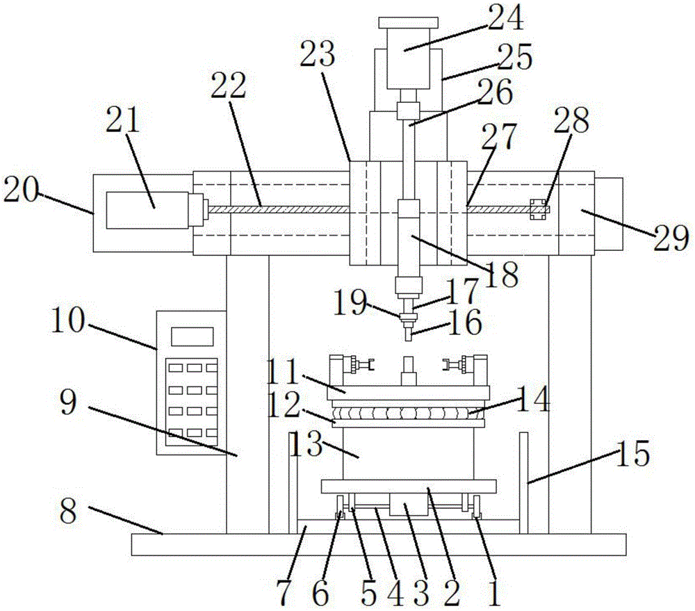
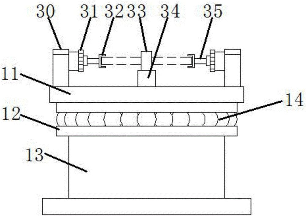
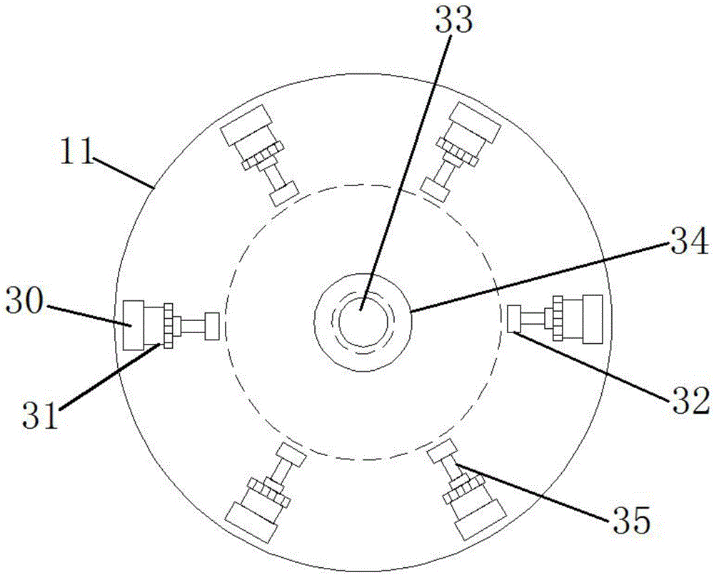
[0018] see Figure 1~3 , in an embodiment of the present invention, a kind of disc-shaped workpiece omni-directional rotary drilling machine tooling, including mobile frame 2, gantry column 9, rotating disk 11, drill bit 16, x-axis sliding seat 23, beam frame 29 and U type claw 32, the top of the gantry column 9 is welded with a beam frame 29, the bottom end of the gantry column 9 is fixed on the base 8, and one end of the beam frame 29 is fixed with an assemb...


PUM


Abstract

The invention discloses tooling of a machine tool for omnidirectional rotary drilling of disc-shaped workpieces, which comprises a moving vehicle frame, a gantry column, a rotating disk, a drill bit, an x-axis sliding seat, a beam frame and a U-shaped claw. The top of the gantry column is A beam frame is welded, the bottom end of the gantry column is fixed on the base, an assembly plate is fixed at one end of the beam frame, an x-axis motor is installed on the assembly plate, the x-axis motor is connected to the x-axis screw, and the other end of the x-axis screw passes through The shaft sleeve is installed on the side of the beam frame, and the x-axis sliding seat is installed on the x-axis screw; the drill bit can be adjusted along the x-axis; it is convenient to drive the drilling motor and the drill bit to move up and down along the z-axis, which is convenient for adjusting the height of the drill bit; it is convenient for the drill bit Carry out drilling operations; cooperate with the mobile frame to move along the y-axis, so that the workpiece can be adjusted in the y-axis direction relative to the drill bit, and several U-shaped claws are clamped together to realize the clamping of the workpiece, and it is convenient to drill at different positions on the rotary table Hole work.

Description

technical field [0001] The invention relates to the technical field of mechanical processing, in particular to a tooling of a machine tool for omni-directional rotary drilling of a disc-shaped workpiece. Background technique [0002] Processing machine tools are widely used in the field of mechanical processing, and are effective for processing pipe coils for construction, auto parts, and mold drilling. In the existing processing of disc-shaped workpieces, one is that the workpiece is difficult to fix and clamp, the stability is poor, and the force is easily loosened, resulting in errors in the drilling operation, which leads to an increase in the scrap rate; second, the drilling of the workpiece is time-consuming and laborious. It is necessary to continuously adjust the clamping position of the disc-shaped workpiece and adjust the position of the drill bit, which cannot achieve flexible adjustment of the position of the drill bit, resulting in low processing efficiency of t...

Claims


Application Information

Patent Timeline
IPC IPC(8): B23B39/14B23Q3/08
CPCB23B39/14B23Q3/08
Inventor 田楷
Owner 田楷
Features
  • Generate Ideas
  • Intellectual Property
  • Life Sciences
  • Materials
  • Tech Scout
  • Unparalleled Data Quality
  • Higher Quality Content
  • 60% Fewer Hallucinations
Learn More