Supercharge Your Innovation With Domain-Expert AI Agents!

Chain conveyer transmission structure with mechanical protection function

A technology of chain conveyor and transmission structure, which is applied in the direction of conveyor, transportation, packaging, packaging, etc., which can solve problems such as affecting normal production, increasing maintenance costs, and difficult maintenance of devices, so as to avoid damage to machinery and burn out motors , increase the mechanical protection function, reduce the effect of maintenance cost

Inactive Publication Date: 2017-12-29
卢俭
View PDF0 Cites 0 Cited by
  • Summary
  • Abstract
  • Description
  • Claims
  • Application Information

AI Technical Summary

Problems solved by technology

During the use of the existing chain conveyor transmission structure, a small amount of carried materials often fall and get stuck on the conveyor chain, causing failures, causing frequent actions of motor thermal protection, and even burning out electrical appliances and motors, or breaking chains, etc., affecting Normal production makes device maintenance difficult and increases maintenance costs

Method used


Image

  • Chain conveyer transmission structure with mechanical protection function

Examples


Embodiment Construction

[0010] The present invention will be described in further detail below in conjunction with the accompanying drawings.

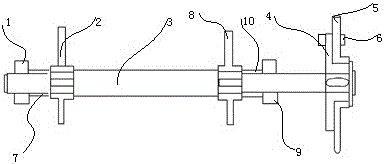
[0011] Such as figure 1 As shown, a chain conveyor transmission structure with mechanical protection function, including the first bearing seat 1, the first conveyor driving sprocket 2, the driving shaft 3, the fixed plate 4, the driving passive sprocket 5, and the protective sheath 6 , the second conveyor drive sprocket 8 and the second bearing seat 9, the drive shaft 3 runs through the first bearing seat 1, the first conveyor drive sprocket 2, the second conveyor drive sprocket 8 and the second bearing In the seat 9, the first bearing seat 1 is compatible with the second bearing seat 9; the first conveyor driving sprocket 2 is compatible with the second conveyor driving sprocket 8; one end of the driving shaft 3 is clamped on the fixed In the disk 4, a driving passive sprocket 5 is arranged on one side of the fixed disk 4, and the fixed disk 4 and the driv...


PUM


Abstract

The invention discloses a chain conveyer transmission structure with a mechanical protection function. The chain conveyer transmission structure comprises a first bearing block (1), a first conveyer driving sprocket (2), a driving shaft (3), a fixing disk (4), a transmission driven sprocket (5), a protective sheath (6), a second conveyer driving sprocket (8) and a second bearing block (9). The driving shaft penetrates through the first bearing block, the first conveyer driving sprocket, the second conveyer driving sprocket and the second bearing block. The first bearing block is matched with the second bearing block. The first conveyer driving sprocket is matched with the second conveyer driving sprocket. One end of the driving shaft is clamped in the fixing disk. One side of the fixing disk is provided with the transmission driven sprocket. The fixing disk and the transmission driven sprocket do up-down relative motion. The protective sheath penetrates through the fixing disk and the transmission driven sprocket and extends to the fixing disk and one end of the transmission driven sprocket. By adopting the chain conveyer transmission structure, machinery damage and motor burnout are avoided, maintenance is easy, and the maintenance cost is reduced.

Description

technical field [0001] The invention relates to the technical field of chain conveyors, in particular to a chain conveyor transmission structure with mechanical protection function. Background technique [0002] Chain conveyor is a conveyor that uses chains to pull and carry materials, or slats, metal mesh belts, rollers, etc. installed on the chains to carry materials. It is widely used in the automatic conveying, distributing, and in-line conveying of subsequent packaging for food, canned food, medicine, beverage, cosmetics and washing products, paper products, condiments, dairy industry and tobacco, etc. During the use of the existing chain conveyor transmission structure, a small amount of carried materials often fall and get stuck on the conveyor chain, causing failures, causing frequent actions of motor thermal protection, and even burning out electrical appliances and motors, or breaking chains, etc., affecting The normal production makes it difficult to maintain the...

Claims


Application Information

Patent Timeline
Patent Type & Authority Applications(China)
IPC IPC(8): B65G23/24
CPCB65G23/24B65G2207/40
Inventor 卢俭
Owner 卢俭
Features
  • R&D
  • Intellectual Property
  • Life Sciences
  • Materials
  • Tech Scout
  • Unparalleled Data Quality
  • Higher Quality Content
  • 60% Fewer Hallucinations
Learn More