
Stationary controls for heating trays and equipment therefor

A control device and tray technology, applied in metal material coating process, coating, gaseous chemical plating and other directions, can solve the problems of unstable tray, tray rollover, tray rollover under force, etc., and achieve convenient pick-and-place control , The effect of improving temperature uniformity and simple structure

Active Publication Date: 2020-01-31
INST OF SEMICONDUCTORS - CHINESE ACAD OF SCI
View PDF4 Cites 0 Cited by
  • Summary
  • Abstract
  • Description
  • Claims
  • Application Information

AI Technical Summary

Problems solved by technology

For low-speed rotating MOCVD, the contact between the tray and the rotating shaft is firm and the rotation is stable; but for high-speed rotating MOCVD, the tray is not firmly fixed to the rotating shaft, and it will be affected by the airflow in the reaction chamber, causing the tray to be unstable.
At the same time, in the electromagnetically heated MOCVD chamber, the tray will also be subjected to periodically changing magnetic force. When the current in the induction coil increases to a certain extent, it may even cause the tray to roll over, which is very important for the growth of thin film materials. Adverse
However, if the tray and the rotating shaft are tightly fixed, it will cause the problem that the film cannot be taken
[0005] For high-temperature electromagnetic heating MOCVD equipment, if the tray is not firmly fixed on the rotating shaft, it will cause the tray to be forced to roll over; however, if it is fixed and non-detachable, it will bring difficulties in sampling by the manipulator

Method used


Image

  • Stationary controls for heating trays and equipment therefor
  • Stationary controls for heating trays and equipment therefor
  • Stationary controls for heating trays and equipment therefor

Examples


Embodiment Construction

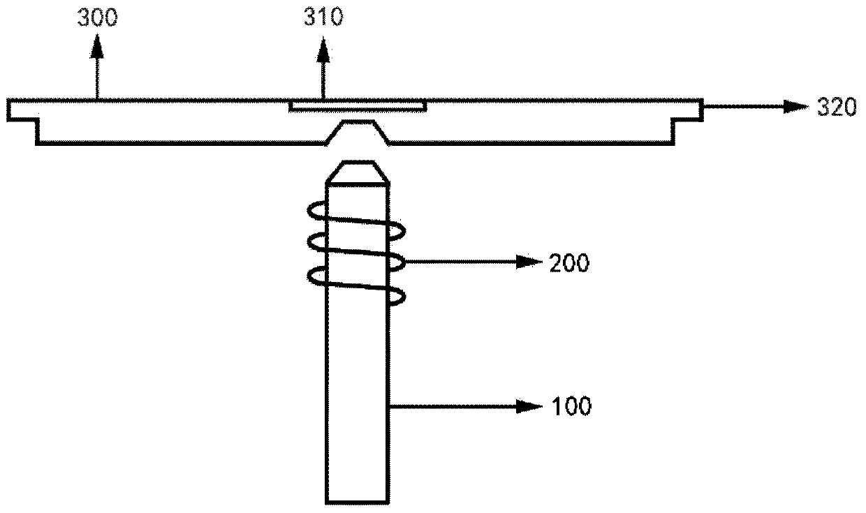
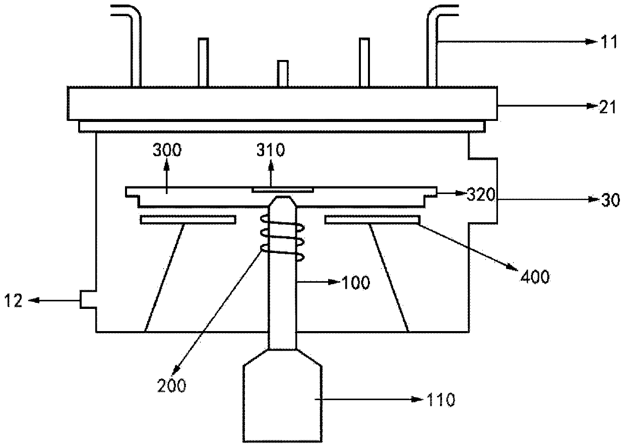
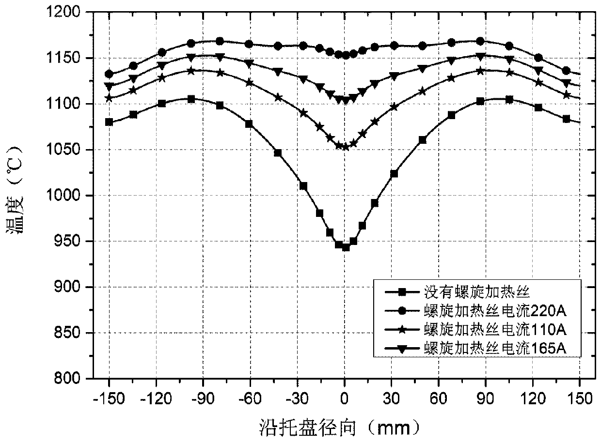
[0032] The disclosure provides a fixed control device for a heating tray and its equipment. By setting a spiral heating wire on the periphery of the rotating shaft that is spaced from the rotating shaft and forming an electromagnet structure, and controlling the on-off of the spiral heating wire, it can realize The fixed state control of the tray and the rotating shaft has a simple structure and is convenient for taking and placing control; at the same time, the heating control of the central area of ​​the tray can be realized by adjusting the current of the spiral heating wire, so as to meet different sizes of trays and different growth temperatures. It can effectively improve the temperature uniformity of the tray.

[0033] In order to make the purpose, technical solutions and advantages of the present disclosure clearer, the present disclosure will be further described in detail below in conjunction with specific embodiments and with reference to the accompanying drawings. ...


PUM

PropertyMeasurementUnit
diameteraaaaaaaaaa

Abstract

The invention discloses a fixing control device for tray heating and equipment of the fixing control device. The fixing control device for the tray heating comprises a rotary shaft, a spiral heating wire, a tray and a ferromagnetic body, wherein the spiral heating wire is arranged on the periphery of the rotary shaft and the spiral heating wire and the rotary shaft are arranged in a spaced manner; and the tray is located over the rotary shaft, and the ferromagnetic body is fixed into the tray and located in a tray center region. The spiral heating wire is arranged on the periphery of the rotary shaft, the spiral heating wire and the rotary shaft are arranged in the spaced manner, and an electromagnet structure is formed; the control over the fixing state of the tray and the rotary shaft can be achieved by controlling the connection and disconnection of the current of the spiral heating wire, the structure is simple, and control over taking and putting is convenient; and meanwhile the current of the spiral heating wire can be adjusted, and the heating control over the tray center region is achieved, so that the requirements of the different trays and different growth temperatures are met, and the temperature uniformity of the tray can be improved effectively.

Description

technical field [0001] The disclosure belongs to the field of thin film material growth equipment manufacturing, and relates to a fixing control device for a heating tray and equipment thereof. Background technique [0002] Metal-organic chemical vapor deposition (MOCVD) equipment is one of the key equipment for the epitaxial growth of compound semiconductor materials, especially suitable for large-scale production in the semiconductor industry. The most important equipment such as compound semiconductors. [0003] In the production process, the sample feeding and sampling operation of the substrate wafer grown with thin film material is an essential step. The substrate is generally placed in a circular pit on the upper surface of the tray, and the tray is heated to raise the temperature. The heat conduction between the tray and the substrate causes the temperature of the substrate to rise, thereby providing the growth of the thin film material on the substrate. required t...

Claims


Application Information

Patent Timeline
Patent Type & Authority Patents(China)
IPC IPC(8): C23C16/46C23C16/458C23C16/52
CPCC23C16/4581C23C16/46C23C16/52
Inventor 王晓亮梅书哲肖红领王权殷海波李巍姜丽娟
Owner INST OF SEMICONDUCTORS - CHINESE ACAD OF SCI
Learn More