
Shaft supporting base and device with shaft

A shaft support and installation groove technology, which is applied to the components of the pumping device for elastic fluids, non-variable volume pumps, machines/engines, etc., can solve the problems of inconvenient operation and time-consuming, and achieve easy disassembly Effect

Pending Publication Date: 2017-12-29
GREE ELECTRIC APPLIANCES INC
View PDF8 Cites 1 Cited by
  • Summary
  • Abstract
  • Description
  • Claims
  • Application Information

AI Technical Summary

Problems solved by technology

[0004] Therefore, the technical problem to be solved by the present invention is to overcome the disadvantages of inconvenient and time-consuming operations in which the wind wheel assembly is separately disassembled from the body in the prior art, thereby providing a shaft that is convenient to disassemble the shaft from the body for cleaning. Support base and device with shaft installed

Method used


Image

  • Shaft supporting base and device with shaft
  • Shaft supporting base and device with shaft
  • Shaft supporting base and device with shaft

Examples


Embodiment 1

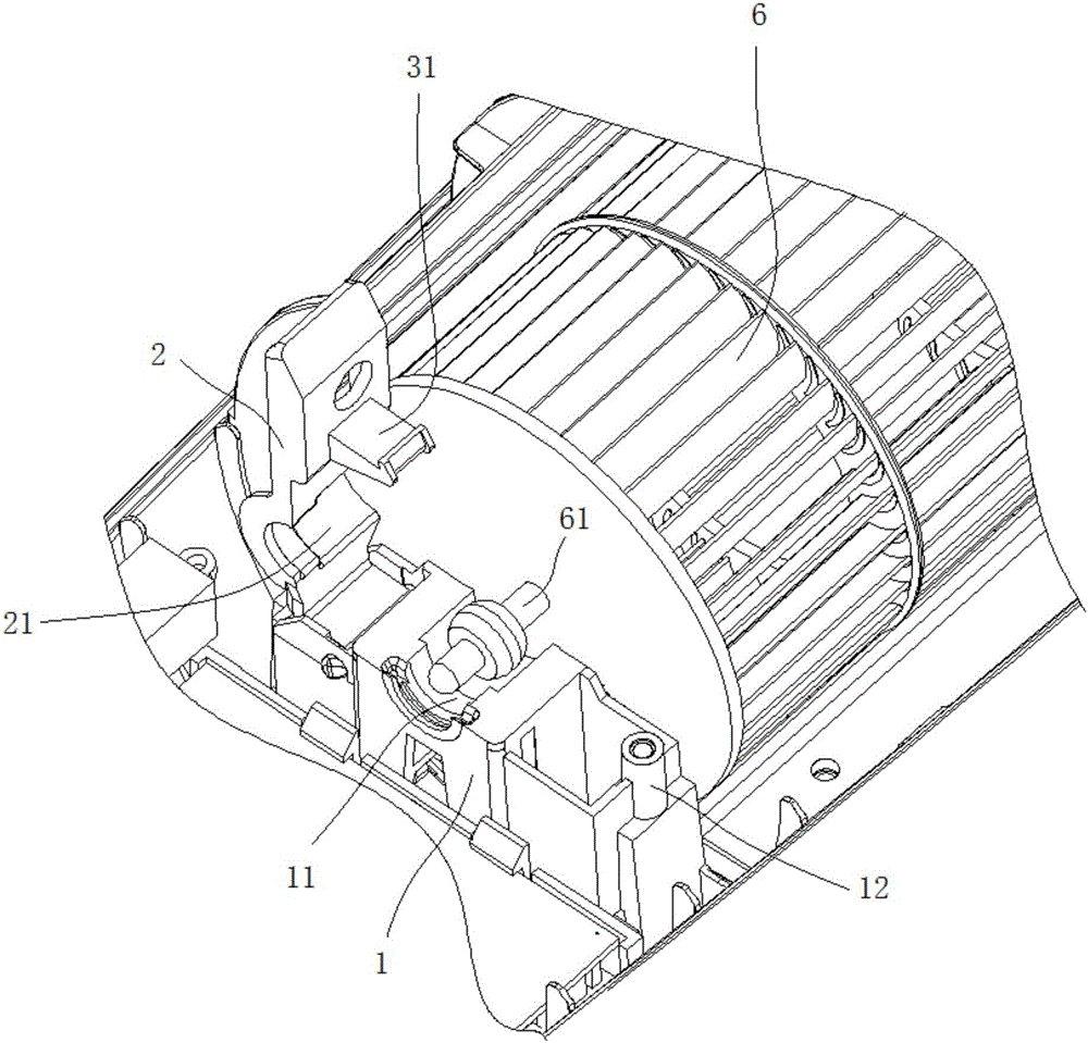
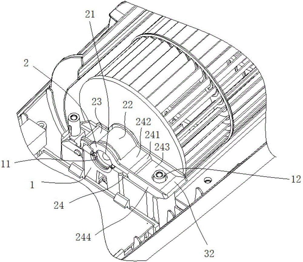
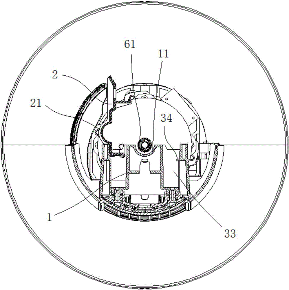
[0037] Such as Figure 1-Figure 4 As shown, this embodiment provides a shaft support seat, including a fixed seat 1 and a movable seat 2 .

[0038] The fixing base 1 is provided with a first installation groove 11 .

[0039] The movable seat 2 is provided with a second mounting groove 21, one end of which is hinged to the fixed seat 1, and the other end is detachably connected to the fixed seat 1 through a buckle structure, and when the buckle structure is engaged, the The second installation groove 21 cooperates with the first installation groove 11 to form a shaft hole suitable for accommodating the shaft; when the buckle structure is released, the movable seat 2 can move toward the second installation groove under the action of external force. The installation slot 21 moves in a direction of disengaging from the first installation slot 11 . As an alternative embodiment, it is also possible that the two ends of the movable seat 2 are detachably connected to the fixed seat ...

Embodiment 2

[0047] Such as Figure 1-Figure 4 As shown, this embodiment provides a device with a shaft installed, including two docking parts and the shaft support seat described in Embodiment 1, wherein the shaft support seat described in Embodiment 1 is arranged on the two docking parts In between, the fastened movable seat 2 and the fixed seat 1 are pressed tightly through the detachable butt joint of the two docking parts.

[0048] The specific forms of the two docking parts can be various. In this embodiment, the two docking parts are respectively the first housing 4 and the second housing 5 of the device with the shaft installed, and the fixing seat 1 is set on the first shell 4, and the second shell 5 is provided with a pressing block 51, after the first shell 4 is docked with the second shell 5, the pressing block 51 and The first housing 4 cooperates to press the fastened movable seat 2 and the fixed seat 1 tightly. The setting of the pressure block 51 can make the cooperation ...


PUM


Abstract

The invention provides a shaft supporting base and a device with the shaft supporting base and provided with a shaft. The shaft supporting base comprises a fixed base and a movable base; the fixed base is provided with a first mounting groove; the movable base is provided with a second mounting groove, at least one end of the movable base is detachably connected with the fixed base through a buckle structure, when the buckle structure is buckled, the second mounting groove and the first mounting groove are matched to form a shaft hole suitable for containing the shaft, and when the buckle structure is released, under the effect of external force, the movable base can move in the direction where the second mounting groove is separated from the first mounting groove. According to the shaft supporting base and the device with the shaft supporting base and provided with the shaft, the shaft can be stably supported, and the shaft can be dismounted and mounted conveniently.

Description

technical field [0001] The invention relates to the technical field of household appliances, in particular to a shaft support seat and a device on which the shaft is installed. Background technique [0002] A tower fan is a type of fan, which usually includes a body and a wind wheel assembly installed in the body. The wind wheel assembly is fixed inside the body together with the air duct. Although such a structure is stable, the wind wheel assembly cannot be disassembled from the body. It is not easy to clean the wind wheel assembly. When the tower fan is used for a period of time, a lot of dust will accumulate on the wind wheel assembly inside the body, so that the wind blown by the tower fan that has been used for a long time is full of dust. Make the living environment worse, also have greater harm to the human body. [0003] The patent document with the publication number CN204692129U discloses a tower fan whose wind wheel assembly is easy to disassemble and clean, inc...

Claims


Application Information

Patent Timeline
IPC IPC(8): F04D29/05F04D29/62
CPCF04D29/05F04D29/626
Inventor 黄忠平符星珂张培德陈正超麦焕徐余良陈志聪罗汉兵凌业生郭晗
Owner GREE ELECTRIC APPLIANCES INC
Learn More