Positioning system and positioning method for optical module for automobile lamp

A technology of optical components and positioning systems, applied in the direction of headlights, light source fixing, vehicle parts, etc., can solve the problem of not meeting the installation accuracy of optical modules in the headlights, physical light distribution not meeting regulatory requirements, LED circuit boards and concentrating light. To solve the problem of large assembly tolerance of the device, it can achieve the effect of less assembly dimension chain, reducing assembly error and improving positioning accuracy.

Pending Publication Date: 2017-12-29
HASCO VISION TECHNOLOGY CO LTD
View PDF11 Cites 22 Cited by
  • Summary
  • Abstract
  • Description
  • Claims
  • Application Information

AI Technical Summary

Problems solved by technology

In this way, from the perspective of tolerance analysis, the final assembly tolerance between the LED circuit board and the concentrator is relatively large, which cannot meet the installation accuracy requirements of the optical module in the car lamp, resulting in the physical light distribution not meeting the regulatory requirements.

Method used


Image

  • Positioning system and positioning method for optical module for automobile lamp
  • Positioning system and positioning method for optical module for automobile lamp
  • Positioning system and positioning method for optical module for automobile lamp

Examples


Embodiment

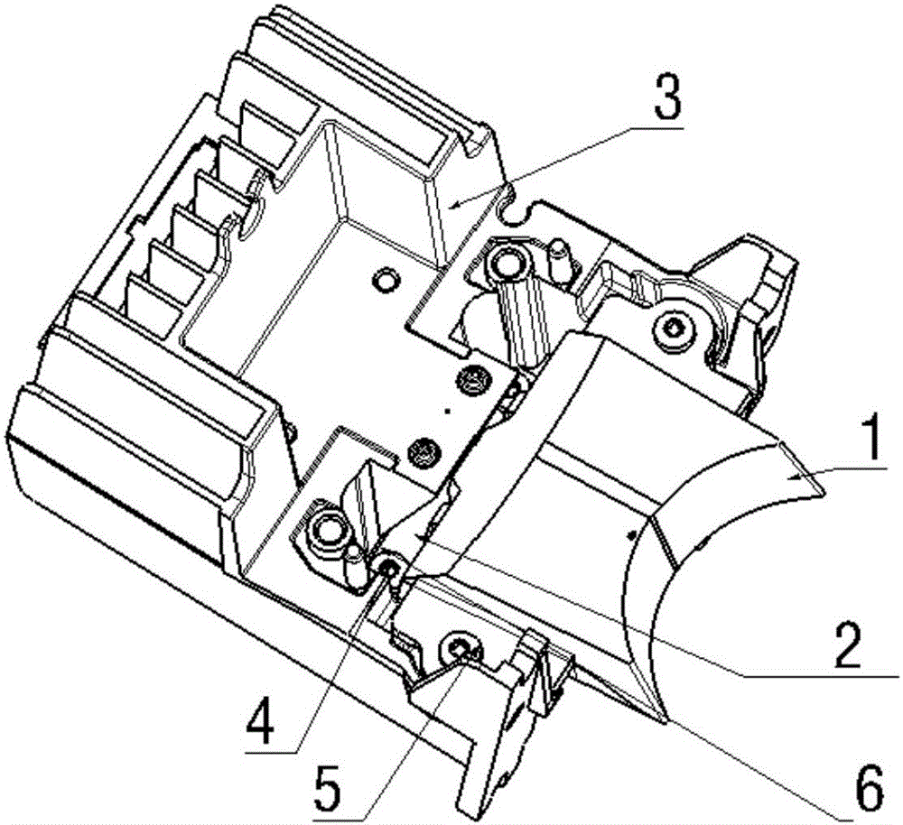
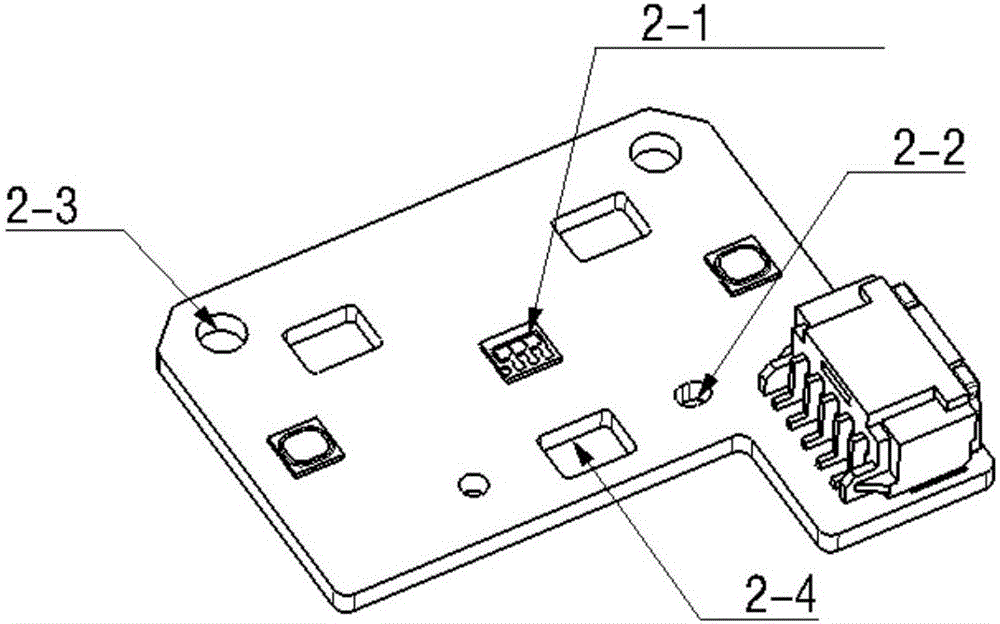
[0073] An optical component positioning system for vehicle lights, comprising: an optical component (1), an LED board (2) and a mounting bracket (3), the LED board (2) is arranged under the optical component (1), and the optical component (1) and The LED board (2) forms a detachable small assembly (7) for installation, which is directly positioned and installed on the installation bracket (3) with the positioning sleeve.

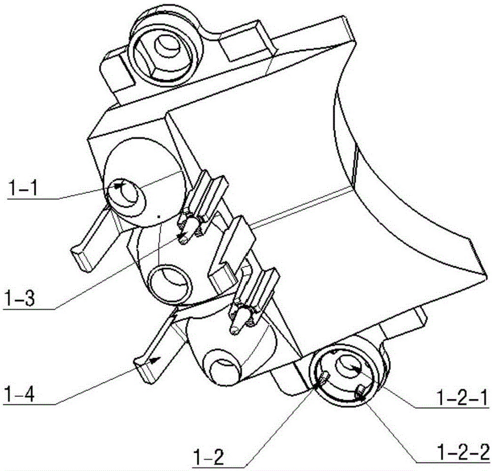
[0074] According to this embodiment, the optical assembly (1) includes a light incident system element (1-1), a positioning sleeve (1-2), a positioning pin (1-3) and a hook (1-4). The positioning sleeve (1-2) is arranged on both sides of the optical assembly (1), and has screw holes (1-2-1) and positioning ribs (1- 2- 2). The detachable small assembly for installation (7) is positioned and installed on the mounting bracket (3) through the positioning ribs (1-2-2), and the positioning pins (1-3) and hooks (1-4) are set on the optical The lower part of the c...


PUM


Abstract

The invention discloses a positioning system for an optical module for an automobile lamp. The positioning system comprises the optical module (1), an LED panel (2) and an installing bracket (3). The positioning system is characterized in that the LED panel (2) is arranged below the optical module (1), the optical module (1) and the LED panel (2) form a small detachable installing assembly (7), and the small detachable installing assembly (7) is directly positioned and installed on the installing bracket (3) through positioning sleeves. According to the positioning system, the LED panel (2) and the optical module (1) are directly positioned through positioning pins and pre-fixed through hooks, the optical module (1) and the LED panel (2) are directly positioned, therefore, the position precision of the optical module (1) and the LED panel (2) is relatively high, the assembling error is reduced, and the positioning precision of an optical system is improved.

Description

technical field [0001] The present invention relates to the design of an optical module, in particular, the present invention relates to a design of an optical module in a car lamp, the design of the optical module in a car lamp can be used for an optical positioning system in a car light, and the optical positioning system in a car light The optical positioning system in the lamp has high assembly accuracy. Background technique [0002] At present, in the design of car lights, LEDs are generally used as light sources. LED light sources have the advantages of long life, wide brightness range, and adaptability to various car light shapes. As a mandatory part of the regulations, the car lights must meet the light distribution value specified by the regulations for each function. In order to ensure the reliability and uniqueness of the light distribution of the actual parts, the design needs to ensure the position of the LED and the positioning accuracy of the optical parts. ...

Claims


Application Information

Patent Timeline
Patent Type & Authority Applications(China)
IPC IPC(8): F21S8/10F21V17/10F21V17/12F21V17/16F21V7/10F21V5/04F21W101/02F21Y115/10
CPCF21V5/04F21V7/10F21V17/10F21V17/12F21V17/164F21Y2115/10F21S41/29F21S41/24F21S41/322F21S45/47F21S41/148F21S41/19
Inventor 张大攀仇智平
Owner HASCO VISION TECHNOLOGY CO LTD
Why Eureka
Try Eureka