Energy gathering ring for gas stove

A technology of energy-gathering rings and gas stoves, applied in the field of gas stoves, can solve the problems of insufficient combustion of gas, easy generation of yellow flames, and lack of passages for air to enter the burner, etc., to achieve simple structure, convenient disassembly and assembly, and promote full combustion Effect

Pending Publication Date: 2017-12-29
ZHEJIANG CHOOSITON KITCHEN ELECTRIC APPLIANCE CO LTD
View PDF0 Cites 5 Cited by
  • Summary
  • Abstract
  • Description
  • Claims
  • Application Information

AI Technical Summary

Problems solved by technology

However, the energy-gathering annular plate of the existing energy-gathering ring is a solid plate, and the energy-gathering annular plate also prevents air from entering the burner while reducing air loss, and is more likely to produce yellow flames caused by insufficient combustion of gas; in addition, due to The burner is located in th

Method used


Image

  • Energy gathering ring for gas stove
  • Energy gathering ring for gas stove
  • Energy gathering ring for gas stove

Examples


Embodiment 1

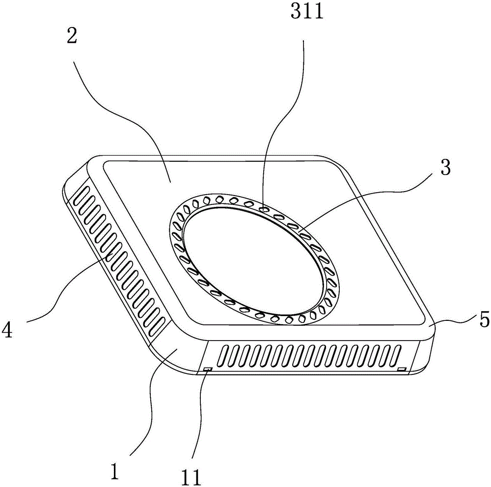
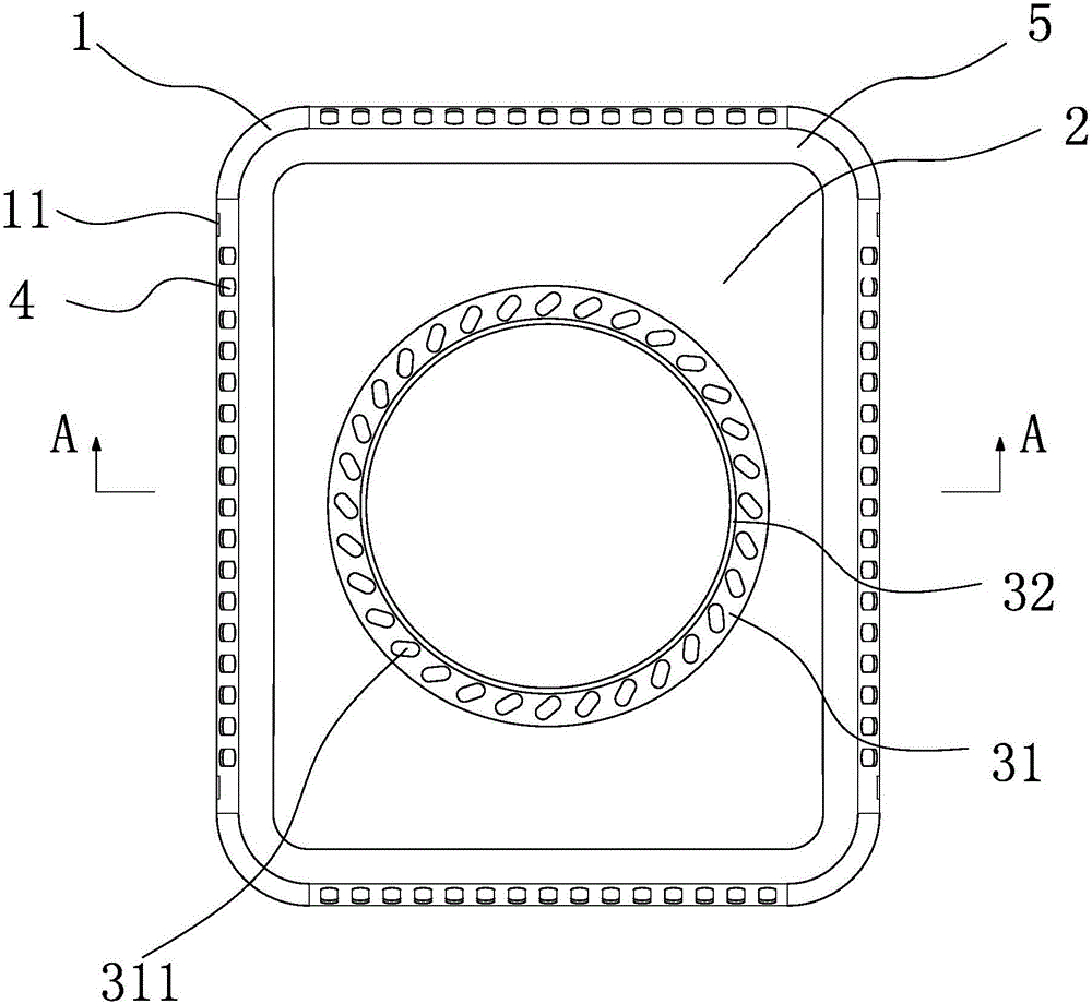
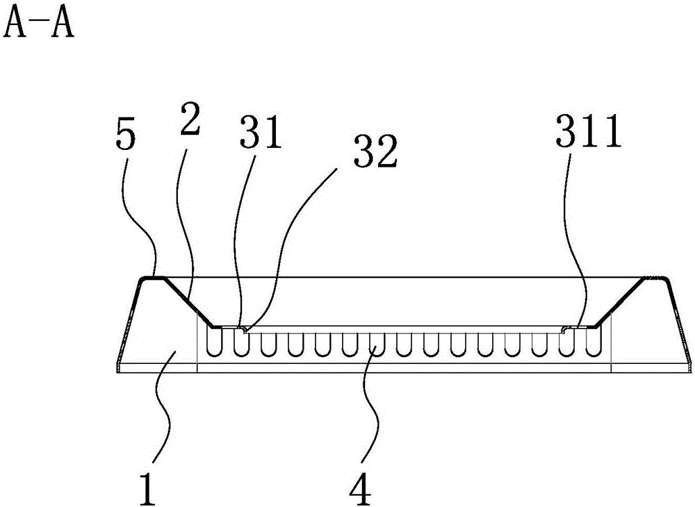
[0027] refer to figure 1 and figure 2 , the first embodiment is an energy-gathering ring for a gas stove, including a support frame ring 1, an energy-gathering portion 2 and a positioning ring portion 3, the support frame ring 1 is rectangular, and the support frame ring 1 has a connection bayonet 11, which is used Placed on the table top of the gas stove and supports the pan support, the positioning ring part 3 is used to be sleeved on the outside of the burner, the energy gathering part 2 is located on the periphery of the positioning ring part 3, and is located inside the support frame ring 1, The energy gathering part 2 is ring-shaped, and the energy gathering part 2 is inclined downward from the outside to the inside, the inner edge of the energy gathering part 2 is connected with the positioning ring part 3, and the outer edge of the energy gathering part 2 is connected with the top end of the support frame ring 1, Moreover, there is a transition ring surface 5 between...

Embodiment 2

[0031] refer to Figure 4 , the structure of the second embodiment is basically the same as that of the first embodiment, the difference is that the vent 4 includes a first vent 41 located in front of the support frame ring 1, and a second vent 42 located at the rear of the support frame ring 1 , the third ventilation opening 43 on the left side of the support frame ring 1 and the fourth ventilation opening 44 on the right side of the support frame ring 1, the third ventilation opening 43 and the fourth ventilation opening 44 are all shaped as strip grooves, and the first The third ventilation opening 43 and the fourth ventilation opening 44 are both arranged obliquely relative to the horizontal plane, and the inclination directions of the third ventilation opening 43 and the fourth ventilation opening 44 are opposite.

[0032] Further, the inclination angles of the third vent 43 and the fourth vent 44 in the second embodiment are the same, and the inclination angle β is 60°-8...

Embodiment 3

[0035] refer to Figure 5 , the structure of the third embodiment is basically the same as that of the second embodiment, the difference is that the outer edge of the transition ring surface 5 connected to the support frame ring 1 has a circle of concave annular groove 6, and the annular groove 6 is used to place the pot rack and limit the pot rack. Since the support frame ring 1 is rectangular, the annular groove 6 is rectangular, which can better erect and limit the rectangular pan support, and prevent the pan support from shifting during use.


PUM


Abstract

The invention provides an energy-gathering ring for gas stoves, which belongs to the technical field of gas stoves. The utility model solves the problem that the heat of the gas is easily lost and the combustion is insufficient when the existing gas stove is in use. The energy gathering ring of the gas stove includes a support frame ring, an energy gathering part and a positioning ring part, the positioning ring part is used to be sleeved on the outside of the burner, and the energy gathering part is located on the periphery of the positioning ring part and inside the support frame ring , the energy-gathering part is ring-shaped, and the energy-gathering part is inclined downward from outside to inside. There are several through-type vents. The energy gathering part can make the flame generated by the burner reflect and gather towards the bottom of the pot, which improves the thermal efficiency; it is introduced from the side of the burner to mix with the gas, which can promote the full combustion of the gas of the burner, and it is not easy to produce yellow flames. high.

Description

technical field [0001] The invention belongs to the technical field of gas stoves, and relates to a fastener, in particular to a locknut. Background technique [0002] At present, in order to improve the thermal efficiency of gas combustion, an energy-gathering ring is added to the liquid pan of the gas stove. The heat in the air, thereby improving the thermal efficiency of combustion. However, the energy-gathering annular plate of the existing energy-gathering ring is a solid plate, and the energy-gathering annular plate also blocks air from entering the burner while reducing air loss, and is more likely to produce yellow flames caused by insufficient combustion of gas; in addition, due to The burner is located in the middle of the liquid pan, and the lower end of the energy gathering ring is in direct contact with the liquid pan. The position where the energy gathering ring is in contact with the liquid pan lacks a channel for air to enter the burner, which further leads ...

Claims


Application Information

Patent Timeline
IPC IPC(8): F24C15/10
CPCF24C15/10
Inventor 高永升
Owner ZHEJIANG CHOOSITON KITCHEN ELECTRIC APPLIANCE CO LTD
Why Eureka
Try Eureka