Current probe and jig suitable for replacing current probe

A technology of current probes and fixtures, which is applied to the parts of electrical measuring instruments, measuring electricity, and measuring electrical variables, etc. It can solve the problems of high operation difficulty and complicated steps of probe head replacement, achieve good positioning function, reduce Replacement efficiency, effective replacement effect

Inactive Publication Date: 2017-12-29
致茂电子(苏州)有限公司
View PDF7 Cites 3 Cited by
  • Summary
  • Abstract
  • Description
  • Claims
  • Application Information

AI Technical Summary

Problems solved by technology

[0004] In view of the above problems, the purpose of the present invention is to provide a current probe and a jig, which help to solve the problems of complicated replacement steps and difficult operation of the probe head

Method used


Image

  • Current probe and jig suitable for replacing current probe
  • Current probe and jig suitable for replacing current probe
  • Current probe and jig suitable for replacing current probe

Examples


Embodiment Construction

[0054] The detailed features and advantages of the present invention are described in detail below in the embodiments, the content of which is sufficient to enable any person skilled in the art to understand the technical content of the present invention and implement it accordingly, and according to the content disclosed in this specification, the patent scope of the application and the drawings , any person skilled in the art can easily understand the related objects and advantages of the present invention. The following examples further illustrate the concept of the present invention in detail, but do not limit the scope of the present invention in any way.

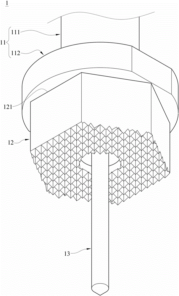
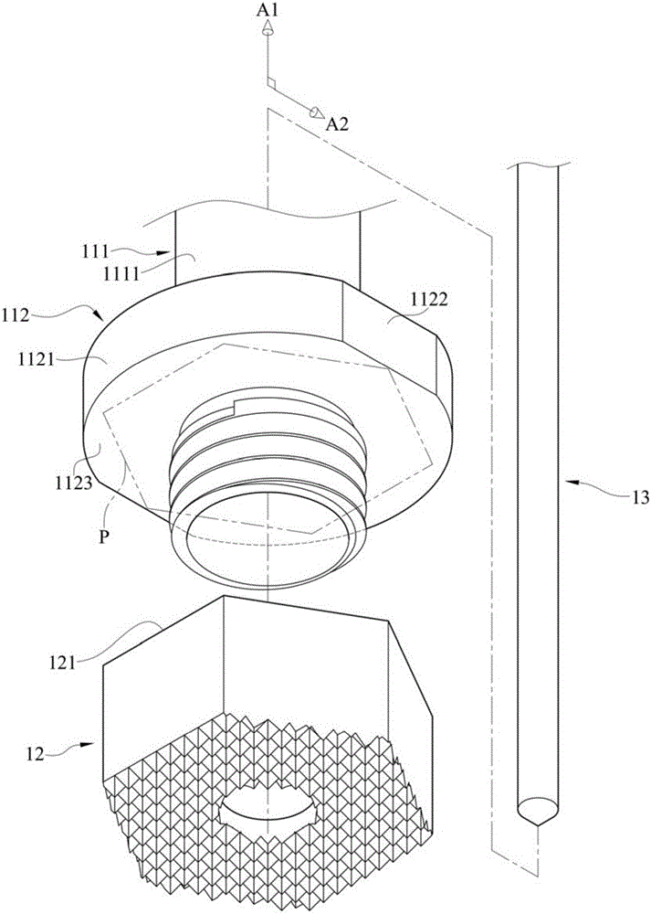
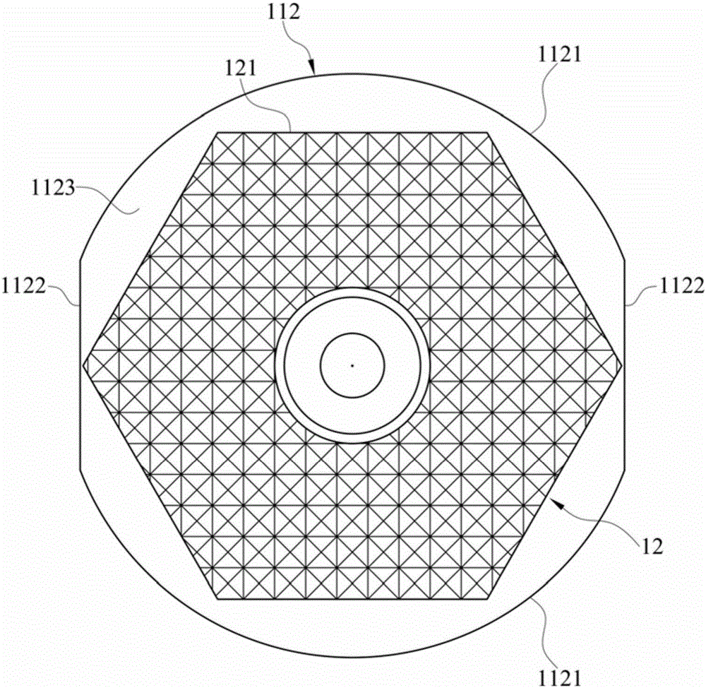
[0055] Please also refer to Figure 1A to Figure 1C . Figure 1A It is a three-dimensional schematic view of the current probe according to the first embodiment of the present invention. Figure 1B for Figure 1A Cutaway schematic of the current probe. Figure 1C for Figure 1A Schematic diagram of the current probe ...


PUM


Abstract

The present invention discloses a current probe and a jig suitable for replacing the current probe. The current probe comprises a base body and a probe head; the base body comprises a main body portion and at least one positioning portion, wherein the positioning portions protrude out from the main body portion; the probe head is detachably disposed on the main body portion of the base body; one side of the probe head, which is far away from the axis of the main body portion, is provided with an outer edge; and the positioning portions protrude out from the outer edge. With the current probe and the jig suitable for replacing the current probe of the invention adopted, the problems of complicated replacement steps and high operational difficulty of the probe head can be solved.

Description

technical field [0001] The invention relates to a current probe and a jig, in particular to a current probe for measuring values ​​such as resistance or voltage, and a jig for replacing the current probe. Background technique [0002] Currently, there are probes for measuring values ​​such as resistance or voltage, especially for large currents (for example, tens of amperes to hundreds of amperes). Before selling products, the industry will use probes to conduct electrical tests to confirm the yield and reliability of the products. In order to reduce heat generation and ensure contact area, etc., during testing, the probe will directly touch the surface of the product to accurately measure resistance or voltage. [0003] Generally speaking, since the needles of the probes will be damaged due to the flow of current during the electrical testing process, they need to be replaced periodically. At present, some probes have a probe head that is detachably mounted on the needle ...

Claims


Application Information

Patent Timeline
Patent Type & Authority Applications(China)
IPC IPC(8): G01R1/067
CPCG01R1/06733
Inventor 许旭昌范姜正陈立勳林川泽王铭辉刘崇琳庄明儒
Owner 致茂电子(苏州)有限公司
Why Eureka
Try Eureka