Low-power consumption weighted pseudo-random test method, system, device and storage medium
A test method and pseudo-random technology, applied in the field of equipment and storage media, systems, and low-power weighted pseudo-random test methods, can solve the problems of not paying attention to low power consumption, energy consumption, etc., and reduce test data capacity and hardware overhead. The effect of low, high fault coverage
Active Publication Date: 2017-12-29
TSINGHUA UNIV
View PDF2 Cites 6 Cited by
- Summary
- Abstract
- Description
- Claims
- Application Information
AI Technical Summary
Problems solved by technology
But these methods usually result in more energy consumption due to frequent flip-flop scans
Method used
View moreImage
Smart ImageViewing Examples
Examples
 PUM
 Abstract
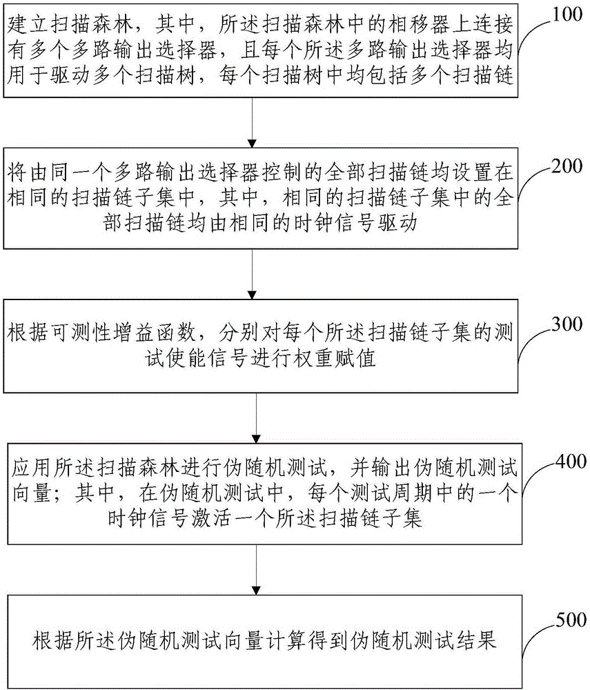
The present invention provides a low-power consumption weighted pseudo-random test method, a low-power consumption weighted pseudo-random test system, a low-power consumption weighted pseudo-random test device and a storage medium. The test method includes the following steps that: a scan forest is established; all scan chains controlled by the same multi-output selector are all set in be the same scan chain subset; weight assignment is performed on test enable signals in each scan chain subset according to a testability gain function; the scan forest is adopted to perform a pseudo-random test, and a pseudo-random test vector is outputted; and a pseudo-random test result is calculated according to the pseudo random test vector. The fault coverage rate of the test method and test system is high and is 20% higher than the fault coverage rate of a traditional method; the low hardware overhead of the test method and test system is low, no additional delay overhead being brought about; the structure of the test method and test system is simple, so that the test method and test system can be widely applied to the industrial community, can be easily embedded into an existing EDA tool, and can support pseudo-random testing and deterministic self-testing; and combined with the deterministic self-testing, the test method and test system can effectively reduce test data capacity.
Description
technical field [0001] The invention relates to the technical field of integrated circuit delay test testability, in particular to a low power consumption weighted pseudo-random test method, system, equipment and storage medium. Background technique [0002] As the circuit scale increases, the gap between functional and test power consumption becomes wider. With the increase of energy consumption, the problem of chip overheating also appeared. Overheating of the chip will shorten the life of the product. Now some more accurate power consumption models have been proposed. One is a fast simulation method for the external interconnect design of low-power chips, and the other is the stacked IC design for the important TSV modeling / simulation technology for low-power 3D networks. However, scan-based self-test techniques (BIST) have higher power consumption than deterministic scan tests due to the increased random code switching activity. [0003] Recent research methods have ...
Claims
Login to View More Application Information
Patent Timeline
 IPC IPC(8): G01R31/28
Inventor 向东刘博
Owner TSINGHUA UNIV
Features
- R&D
- Intellectual Property
- Life Sciences
- Materials
- Tech Scout
- Unparalleled Data Quality
- Higher Quality Content
- 60% Fewer Hallucinations
Learn More Browse by: Latest US Patents, China's latest patents, Technical Efficacy Thesaurus, Application Domain, Technology Topic, Popular Technical Reports.
© 2025 PatSnap. All rights reserved.Legal|Privacy policy|Modern Slavery Act Transparency Statement|Sitemap|About US| Contact US: help@patsnap.com


