Camera tracking method for depth cameras

A technology of depth camera and camera, which is applied in the field of intelligent perception, can solve the problems of limited scope of application and limited scope of application, and achieve the effect of reducing the amount of calculation

Active Publication Date: 2017-12-29
合肥朱曦科技有限公司
View PDF7 Cites 12 Cited by
  • Summary
  • Abstract
  • Description
  • Claims
  • Application Information

AI Technical Summary

Problems solved by technology

However, due to the dependence on the existing environmental model, the scope of application is relatively limited, and it is not suitable for online motion tracking in the case of unknown environmental models.
[0006] In summary, the method based on visual feature points is more dependent on the rich feature point information in the environment, which severely limits the scope of application.

Method used


Image

  • Camera tracking method for depth cameras
  • Camera tracking method for depth cameras
  • Camera tracking method for depth cameras

Examples


Embodiment Construction

[0041] The technical solutions of the present invention will be described in detail below in conjunction with the accompanying drawings.

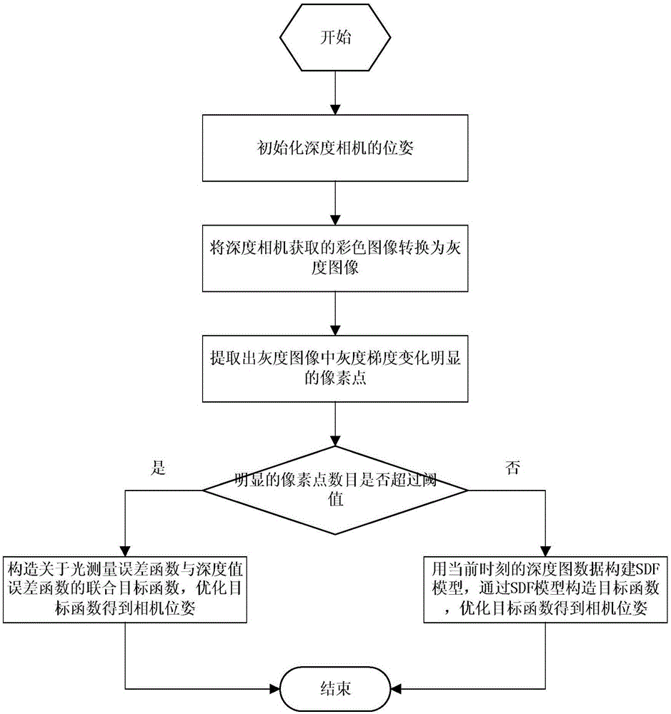
[0042] A camera tracking method for depth cameras, such as figure 1 As shown, the specific steps are as follows.

[0043] Step 1: Initialize the pose of the depth camera.

[0044] Step 2: Convert the color image acquired by the depth camera to a grayscale image.

[0045] Step 3: Extract the pixels in the grayscale image whose grayscale gradient changes are greater than the set threshold a, and use these pixels as pixels with obvious grayscale gradient changes.

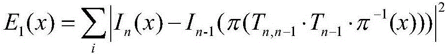
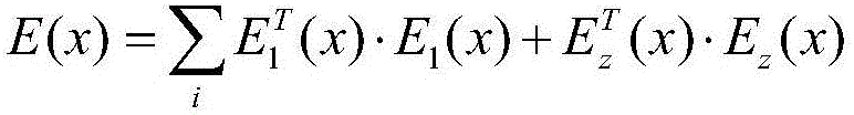
[0046]Step 4: If the number of pixels with obvious gray gradient changes is greater than the set threshold b, then for pixels with obvious gray gradients, construct a light measurement error function and a depth value error function, and use the two norms of these two functions Construct a joint objective function, optimize the joint objective function to estimate the change of c...


PUM


Abstract

The invention discloses a camera tracking method for depth cameras. A camera tracking mode based on visual information or a camera tracking mode based on depth information is chosen according to whether the feature points of a gray image are obvious. A joint objective function about optical measurement error and depth value error is constructed in the camera tracking mode based on visual information. An objective function about a signed distance function model is constructed in the camera tracking mode based on depth information. Through dual-mode switching, the applicability of the system is enhanced, and the stability of the system is improved.

Description

technical field [0001] The invention belongs to the technical field of intelligent perception, and in particular relates to a camera tracking method oriented to a depth camera. Background technique [0002] Using a depth camera to construct a visual odometry to track camera movement is an increasingly popular method in Visual SLAM (Simultaneous Localization and Mapping) technology. Accurate camera pose estimation is the basis of environment modeling and an important research object in Visual SLAM. For camera motion tracking, the commonly used method is to extract and match discrete sparse visual features, then use the reprojection error to construct an objective function, and then solve the minimum value of the objective function to estimate the camera pose. The effectiveness and accuracy of this type of method depend on the key points and descriptors of image features; in the process of feature extraction, large computing resources will be consumed. [0003] Chinese paten...

Claims


Application Information

Patent Timeline
Patent Type & Authority Applications(China)
IPC IPC(8): G06T7/70
CPCG06T7/70
Inventor 李朔杨高峰李骊周晓军王行
Owner 合肥朱曦科技有限公司
Why Eureka
Try Eureka