Dedicated load box for electricity consumption inspection

It is a technology of electricity inspection and load box, which is applied in the direction of electrical components, measuring electrical variables, and structural parts of electrical equipment. It can solve problems such as easy accumulation of dust, increased capital expenditure, and reduced heat dissipation effect, so as to ensure heat dissipation effect, Improve heat dissipation efficiency and prolong service life

Inactive Publication Date: 2017-12-29
STATE GRID SHANDONG ELECTRIC POWER CO PINGYUAN POWER SUPPLY CO +1
View PDF3 Cites 0 Cited by
  • Summary
  • Abstract
  • Description
  • Claims
  • Application Information

AI Technical Summary

Problems solved by technology

The load and fans in the existing load box have been installed and set. In order to ensure the smooth progress of the measurement, it is necessary to install a larger fan or multiple fans in the load box. There are more fans in the load box with a larger load. There are fewer fans installed in the load box with a small load, and the load box is relatively bulky, which is inconvenient to transport. It is more difficult to transport when testing in areas such as the wild or rural areas that are more tortuous and inconvenient for large vehicles to enter. The transportation and use of load boxes with smaller loads, although the transportation is more convenient, may cause the load to disengage due to poor heat dissipation, prolonging the test time, and, according to the different loads expected to be tested, use different load boxes , which increases the capital expenditure and increases the equipment idle rate
In addition, in order to improve the heat dissipation effect of the existing load box, a large area of ​​heat dissipation holes is provided on the side wall of the load box. Although the heat dissipation effect is improved, the probability of dust entering the load box is increased, so that zero in the load box Parts are easy to accumulate dust, which reduces the heat dissipation effect

Method used


Image

  • Dedicated load box for electricity consumption inspection
  • Dedicated load box for electricity consumption inspection
  • Dedicated load box for electricity consumption inspection

Examples


Embodiment

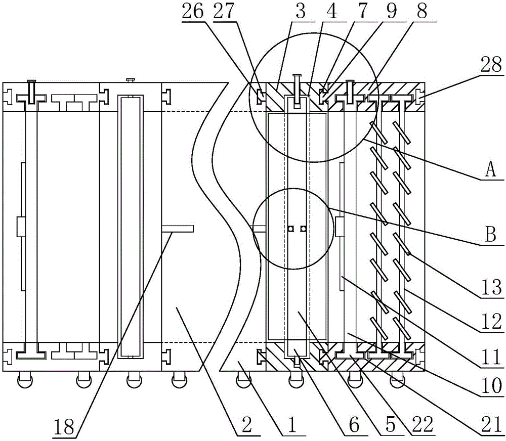
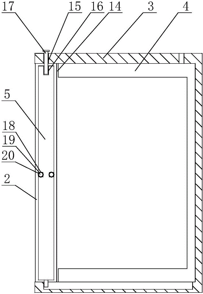
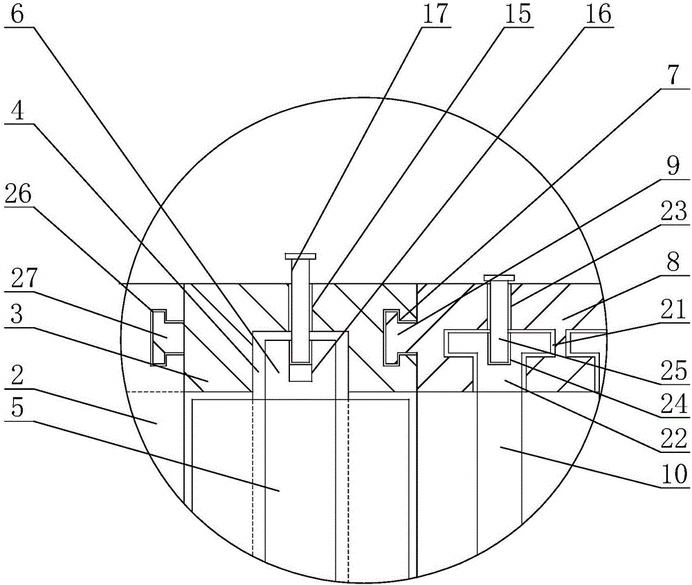
[0044]A special load box for electrical inspection, including a bottom plate 1, on which a U-shaped box body 2 with an opening downward is arranged, which can be realized by welding or bolting, and the bottom plate and the box body can be made of high temperature resistant materials. The cavity formed by the box body 2 and the bottom plate 1 is provided with a resistance element for testing, and the side wall of the box body 2 is provided with an extension hole 18. One end of the box body 2 and the side end of the bottom plate 1 Both are provided with a fourth chute 26, a baffle bracket 3 is provided between the bottom plate 1 and the box body 2, and a fourth slider 27 adapted to the fourth chute 26 is provided on the baffle bracket 3, It can be realized by welding or bolted connection, the baffle bracket 3 can slide along the fourth chute 26, one side of the baffle bracket 3 is provided with an opening, and the horizontal upper horizontal plate of the baffle bracket 3 The bot...


PUM

PropertyMeasurementUnit
Slopeaaaaaaaaaa

Abstract

The invention discloses a dedicated load box for electricity consumption inspection, and mainly relates to the field of power supply. The load box comprises a bottom plate, and the bottom plate is provided with a box body. A resistor element for testing is disposed between the box body and the bottom plate, and a baffle plate support is disposed between the bottom plate and the box body. One side of the baffle plate support is provided with an opening, and the baffle plate support is provided with two first chutes. A baffle plate is disposed between the two first chutes, and can slide along the first chutes. The baffle plate support is provided with two second chutes, and a heat dissipation support is disposed between the second chutes. The heat dissipation support is provided with a second sliding block, and can slide outwards along the second chutes. The heat dissipation support is provided with a plurality of fan supporting rods, and the fan supporting rods are provided with rotating shafts which are provided with fan blades. The fan blades are connected with a drive motor. The heat dissipation support is provided with a plurality of dust prevention supporting rods, and the dust prevention supporting rods are provided with dust prevention pieces in an inclined manner. The beneficial effects of the invention are that the load box can separate the fans for heat dissipation and a load box main unit conveniently, facilitates the transportation, reduces the probability that dust enters the load box, and improves the heat dissipation effect.

Description

technical field [0001] The invention relates to the field of power supply, in particular to a special load box for electricity inspection. Background technique [0002] The correctness and accuracy of the electric energy metering device are directly related to the economic interests of both the power supply and the consumer. The testers use the special load box for electricity inspection to test the actual load capacity of the equipment to accurately test the accuracy of the meter. The load box contains a large number of test resistance elements, which are composed of hundreds of nickel-chromium resistance wires. When the resistance wires are subjected to load testing, a large amount of heat will be generated. A cooling fan is installed on the load box, and the fan is forced to cool to ensure its Normal operation, when the temperature inside the load box exceeds the limit set by the thermostat, the load will be disconnected and the test will be stopped. The load and fans in...

Claims


Application Information

Patent Timeline
IPC IPC(8): H05K7/20G01R11/02G01R11/12
CPCH05K7/20172G01R11/02G01R11/12
Inventor 刘光磊徐晓蕊李涛李勇王鹏张学杰梁晓张丽刘健张栋
Owner STATE GRID SHANDONG ELECTRIC POWER CO PINGYUAN POWER SUPPLY CO
Why Eureka
Try Eureka