Method for controlling standing-phase damping of artificial knee joint

A knee joint, artificial technology, applied in artificial legs, appliances to help people walk, medical science, etc., can solve the problems of hip joint impact load, reduced wearing comfort and acceptance of prosthetics or orthoses, etc. The effect of small bending resistance

Active Publication Date: 2018-01-02
OTTO BOCK HEALTHCARE PROD GMBH
View PDF12 Cites 2 Cited by
  • Summary
  • Abstract
  • Description
  • Claims
  • Application Information

AI Technical Summary

Problems solved by technology

However, too high an initial flexion damping, i.e. damping against the flexion of the artificial knee joint, can lead to impact-like loads in the hip joint, which can lead to reduced wearing comfort and acceptance of the prosthetic or orthotic

Method used


Image

  • Method for controlling standing-phase damping of artificial knee joint
  • Method for controlling standing-phase damping of artificial knee joint

Examples


Embodiment Construction

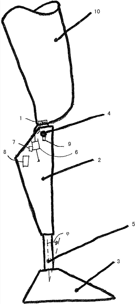
[0026] exist figure 1 In FIG. 2 , a leg prosthesis is shown schematically with an upper part 1 on which a thigh tube 10 for receiving the thigh stump is fastened. A lower part 2 in the shape of a lower leg part is arranged pivotably on the upper part 1 . On the upper part 1 , the lower part 2 is mounted pivotably about a pivot axis 4 . The lower part 2 has a calf tube 5, on the distal end of which a prosthetic foot 3 is fastened, in which a device for determining the effective axial force acting on the calf tube 5 and for determining the ankle can be inserted. The device of moment, this ankle moment acts around the fixation point of prosthetic foot 3 on calf tube 5.

[0027] Arranged in or on the lower part 2 is a resistance device 6 , which can be configured, for example, as a damper or an actuator, which is supported between the upper part 1 and the lower part 2 in order to provide an adjustable extension resistance and bending resistance. An adjusting device 7 is assigne...


PUM


Abstract

The invention relates to a method for controlling the standing-phase damping of an artificial knee joint. The artificial knee joint comprises an upper part (1) and a lower part (2) which are secured together in a pivotal manner about a pivot axis (4), and is provided with a resistance unit (6) which is arranged between the upper part (1) and the lower part (2) and has an adjustment device (7) viawhich the damping resistance (FD) can be modified, and a control unit (8) which is coupled to the adjustment device (7) and which is connected to at least one sensor (9). The adjustment is carried outon the basis of sensor data, and the knee angle (alpha) is detected by the at least one sensor (9) during the standing-phase inflexion up to the terminal standing phase. The flexion damping (FD) is increased to a level (FDmax) above an initial flexion damping (FDI) in order to prevent a further inflexion upon reaching a specified maximum knee angle ([alpha]max).

Description

technical field [0001] The invention relates to a method for controlling the stance phase damping of an artificial knee joint having an upper part and a lower part which are pivotably fixed to each other about a pivot axis and having a resistance unit arranged between the upper part and the lower part. Between the lower part and with an adjustment device via which the damping resistance can be varied, the artificial knee joint also has a control unit coupled to the adjustment device and connected to at least one sensor, wherein the adjustment takes place on the basis of sensor data. Background technique [0002] A knee joint for an orthosis, an exoskeleton or a prosthesis has an upper part with an upper connection part and a lower part with a lower connection part, which are hingedly connected to one another. A receptacle for the thigh stump or thigh rail is usually arranged on the upper connecting part, and a lower leg tube or lower leg rail is arranged on the lower connect...

Claims


Application Information

Patent Timeline
IPC IPC(8): A61F2/64A61F2/68A61F2/74A61F2/76
CPCA61F2/64A61F2002/5006A61F2002/5033A61F2002/6818A61F2002/701A61F2002/704A61F2002/705A61F2002/7625A61F2002/7635A61F2002/764A61F2/50A61F2/70A61F2/74A61F2002/5004A61H3/00
Inventor D·塞弗特S·扎林
Owner OTTO BOCK HEALTHCARE PROD GMBH
Why Eureka
Try Eureka