Apparatus for descaling the surface of ingots or rolled products

A sealing surface and pressure chamber technology, applied in workpiece surface treatment equipment, metal rolling, metal rolling, etc., can solve problems such as high axial force, and achieve the effect of improving efficiency and reducing stability

Inactive Publication Date: 2019-04-05
SMS GRP GMBH
View PDF7 Cites 0 Cited by
  • Summary
  • Abstract
  • Description
  • Claims
  • Application Information

AI Technical Summary

Problems solved by technology

[0004] In the described known device for cleaning the surface of an ingot, there is the disadvantage that due to the described construction, when the rotating nozzle holder is loaded with pressure medium for its spray nozzles, it suffers very high axial force

Method used


Image

  • Apparatus for descaling the surface of ingots or rolled products
  • Apparatus for descaling the surface of ingots or rolled products

Examples


Embodiment Construction

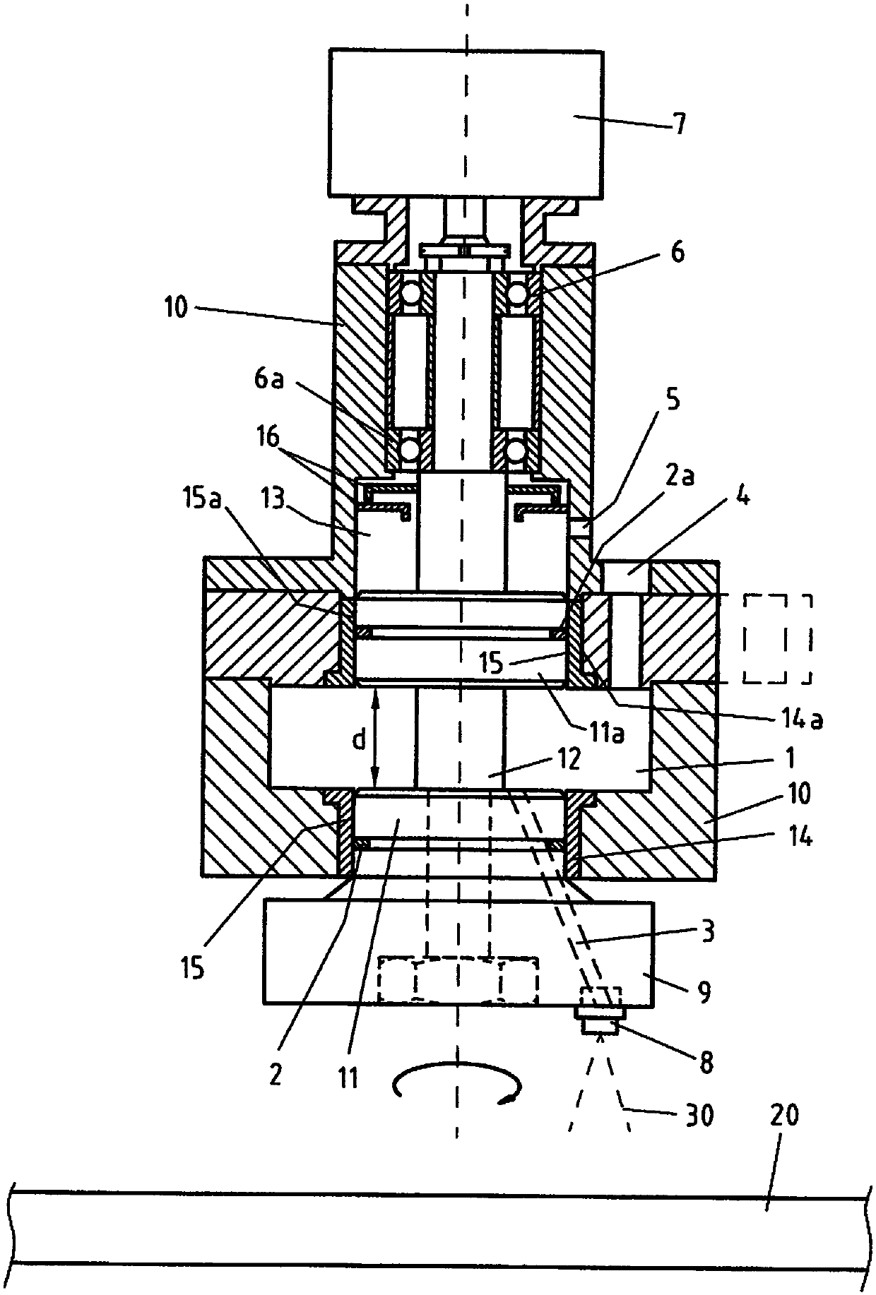
[0021] The invention will be explained in detail below by way of example with reference to the figures mentioned.

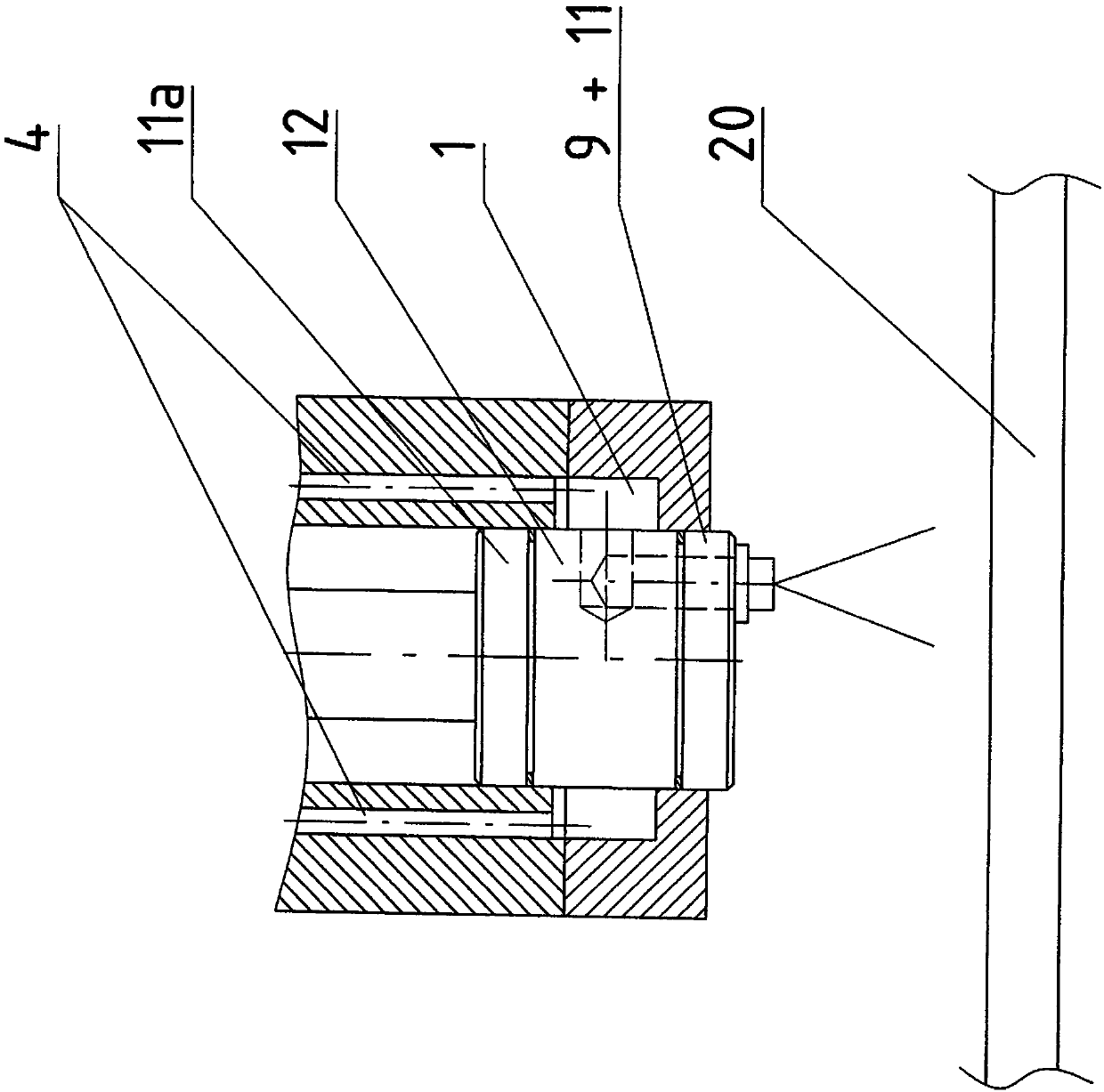
[0022] figure 1 A device according to the invention for cleaning the surface of an object 20 , for example an ingot to be descaled, is shown. The device comprises a housing 10 in which the rotor is mounted via a rotor shaft 12 in bearings 6 , 6 a, which are designed as radial or axial bearings. The first disk 11 and the second disk 11 a each extend radially and are fixed on the rotor shaft 12 at an axial distance d relative to each other. The gap between the first disk and the second disk forms a pressure chamber 1 which can be filled with a pressure medium 30 , for example water, via a supply line 4 . In order to achieve high-pressure cleaning, the pressure medium of the pressure chamber 1 is usually delivered at a high pressure of, for example, 600 bar. The pressure chamber 1 is delimited in the axial direction by two disks 11 , 11 a which are delimited in t...


PUM


Abstract

The invention relates to a device for cleaning the surface of an article. Known devices of this type have a housing (10) with a pressure chamber (1). The rotor shaft is used to rotate a nozzle carrier, which has at least one spray nozzle for spraying the pressure medium onto the surface of the article (20). Between the pressure chamber and the nozzle carrier there is a first plate, which delimits the pressure chamber on one side. In order to avoid the occurrence of great axial forces in the device and in the housing outside the pressure chamber, the invention provides that, apart from the rotor shaft, the rotor comprises the first plate (11) and a second plate (11a), and that the first and second plates (11, 11a) are fastened on the rotor shaft (12) at an axial distance d from one another respectively with radial extent, wherein the pressure chamber (1) extends in the intermediate space defined by the two plates.

Description

technical field [0001] The invention relates to a device for cleaning surfaces of objects, in particular for descaling rolled stock or ingots, ie parts of continuous cast slabs in rolling mills. Background technique [0002] Such devices are known in principle from the prior art, for example from Austrian patent document AT406234B. The device disclosed in this document comprises a housing in which a pressure chamber for a pressure medium is formed. The pressure chamber is supplied with pressure medium via the feed line. The rotor shaft is rotatably mounted within the housing by means of at least one bearing. A nozzle holder is attached to the rotor shaft, which nozzle holder has at least one spray nozzle for spraying pressure medium onto the surface of the object. A first plate delimiting the pressure chamber on one side is arranged between the pressure chamber and the nozzle holder. The first disk and the nozzle holder have mutually flush delivery channels for deliverin...

Claims


Application Information

Patent Timeline
Patent Type & Authority Patents(China)
IPC IPC(8): B21B45/08
CPCB21B45/06B21B45/08
Inventor R·弗朗茨W·米歇尔W·富克斯
Owner SMS GRP GMBH
Why Eureka
Try Eureka