Steam mop boiler

A boiler and mop technology, applied in the direction of cleaning carpets, floors, household appliances, etc., can solve the problems of small vaporization area, and achieve the effects of large vaporization area, good vaporization effect and simple structure

Inactive Publication Date: 2018-01-05
YUYAO JIJIA ELECTRICAL APPLIANCES
View PDF0 Cites 0 Cited by
  • Summary
  • Abstract
  • Description
  • Claims
  • Application Information

AI Technical Summary

Problems solved by technology

[0004] The problem to be solved by the present invention is to provide a steam mop boiler to overcome the defect of small vaporization area in the prior art

Method used


Image

  • Steam mop boiler

Examples


Embodiment Construction

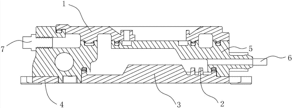
[0012] The specific implementation manners of the present invention will be further described in detail below in conjunction with the accompanying drawings and embodiments. The following examples are used to illustrate the present invention, but are not intended to limit the scope of the present invention.

[0013] Such as figure 1 As shown, a steam mop boiler of the present invention includes an upper casing 1, a heating plate 2, a boiler body 3, a temperature detection device 4 and a heating tube 5; one end of the boiler body 3 is provided with a water inlet 6, and the other end is provided with There is a steam outlet 7; the heating pipe 5 is directly die-casted with the boiler body 3; the upper shell 1 is clamped and fixed with the boiler body 3; the temperature detection device 4 is arranged on the boiler body 3- Side; the heating plate 2 is set in the boiler body 3 .

[0014] The upper casing 1 is made of aluminum alloy. The heat pipe 5 is made of copper.

[0015] Th...


PUM


Abstract

The invention provides a steam mop boiler, which includes an upper casing, a heating plate, a boiler body, a temperature detection device and a heating tube; one end of the boiler body is provided with a water inlet, and the other end is provided with a steam outlet; the heating tube is connected to the The boiler body is directly die-casted; the upper shell and the boiler body are clamped and fixed; the temperature detection device is arranged on one side of the boiler body; the heating plate is arranged in the boiler body. The invention has the advantages of simple structure, large vaporization area and good vaporization effect.

Description

technical field [0001] The invention relates to a steam mop boiler. Background technique [0002] The principle of the steam mop is to heat the water to generate pressure and high temperature, and directly sterilize and sterilize the home environment through high-temperature and high-pressure steam. Steam mops generally have functions such as high-temperature sterilization and oil removal. The steam mop includes a boiler, but the vaporization area of ​​the existing steam mop boiler is small. Contents of the invention [0003] (1) Technical problems to be solved [0004] The problem to be solved by the present invention is to provide a steam mop boiler to overcome the defect of small vaporization area in the prior art. [0005] (2) Technical solution [0006] In order to solve the above technical problems, the present invention provides a steam mop boiler, which includes an upper shell, a heating plate, a boiler body, a temperature detection device and a heating tube; o...

Claims


Application Information

Patent Timeline
Patent Type & Authority Applications(China)
IPC IPC(8): A47L13/22A47L13/42
Inventor 应吉安
Owner YUYAO JIJIA ELECTRICAL APPLIANCES
Why Eureka
Try Eureka