
Nailing clamp for slots

A technology for nailing pliers and wire grooves, applied to the field of wire groove disassembly and assembly tools, can solve the problems of inconvenient wrist movement, wrist joint strain, inconvenient operation, etc. The effect of the nailing effect

Pending Publication Date: 2018-01-05
陆光华
View PDF7 Cites 0 Cited by
  • Summary
  • Abstract
  • Description
  • Claims
  • Application Information

AI Technical Summary

Problems solved by technology

[0002] For now, the heads of the existing rubber pliers are generally straight and have the functions of cutting wires, twisting wires, and clamping iron nails. When using this type of rubber pliers to nail the wire groove, the operation is extremely inconvenient , the straight pliers head clamps the iron nail and forms an acute angle with the iron nail. The operator is easy to hit the pliers head when nailing, which is not conducive to the smooth progress of the nailing process, and at the same time causes damage to the pliers head. If the grip is unstable, the iron nails will fly out, causing certain adverse effects or even losses; when the operator holds the pliers body, because the pliers head is in a straight line, the wrist movement is extremely inconvenient, and the long-term nailing work will cause wrist joint strain , this type of design is not humane enough

Method used


Image

  • Nailing clamp for slots
  • Nailing clamp for slots

Examples


Embodiment Construction

[0023] The specific embodiments of the present invention will be described in detail below in conjunction with the accompanying drawings, but it should be understood that the protection scope of the present invention is not limited by the specific embodiments.

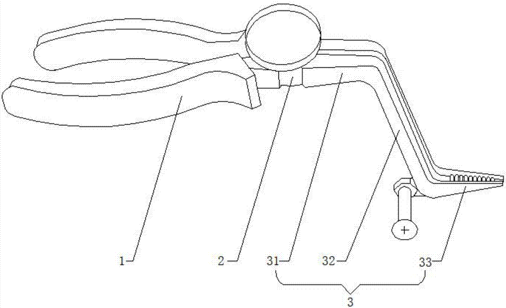
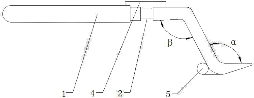
[0024] Embodiments of the present invention are as follows: Figure 1~2 As shown, a wire groove nailing pliers includes a gripping part 1, a rotating shaft 2 and a pliers head 3, and the pliers head 3 includes a thread cutting part 31, a clamping part 33 and a thread cutting part 31, a clip The booster arm 32 between the holding parts 33, wherein the thread cutting part 31 is connected to the rotating shaft 2; the thread cutting part 31 is set on the upper part of the booster arm 32, and the clamping part 33 is set on the booster The lower part of the arm 32. The operation of the present invention is convenient and quick, and when nailing the wire groove, the clamping part can fit the wire groove, the nailing is conve...


PUM


Abstract

The invention discloses a nailing clamp for slots, and belongs to the field of disassembling and assembling tools for the slots. The nailing clamp for the slots comprises a holding portion, a rotatingshaft and a clamp head, and the clamp head comprises wire shearing portions, clamping portions and force-assisting arms arranged between the wire shearing portions and the clamping portions, whereinthe wire shearing portions are connected with the rotating shafts; the wire shearing portions are arranged on the upper portions of the force-assisting arms, and the clamping portions are arranged onthe lower portions of the force-assisting arms. The nailing clamp has the advantages of being safe to operate and achieving convenience and rapidness for nailing on the slots.

Description

technical field [0001] The invention relates to a tool for removing and installing wire grooves, and more specifically, relates to a wire groove nailing pliers. Background technique [0002] For now, the heads of the existing rubber pliers are generally straight and have the functions of cutting wires, twisting wires, and clamping iron nails. When using this type of rubber pliers to nail the wire groove, the operation is extremely inconvenient , the straight pliers head clamps the iron nail and forms an acute angle with the iron nail. The operator is easy to hit the pliers head when nailing, which is not conducive to the smooth progress of the nailing process, and at the same time causes damage to the pliers head. If the grip is unstable, the iron nails will fly out, causing certain adverse effects or even losses; when the operator holds the pliers body, because the pliers head is in a straight line, the wrist movement is extremely inconvenient, and the long-term nailing wor...

Claims


Application Information

Patent Timeline
Patent Type & Authority Applications(China)
IPC IPC(8): B25F1/00
Inventor 陆光华
Owner 陆光华
Learn More