Branch-type shearing-resisting connecting part and application of branch-type shearing-resisting connecting part in preparation of steel-concrete composite structure

A technology of shear connectors and reinforced concrete slabs, which is applied to bridge materials, bridges, buildings, etc., can solve problems such as weak connection capacity, low stiffness, and location damage of steel bars, and achieve convenient construction, strong connection capacity, and cracking problems Effect

Active Publication Date: 2018-01-05
CCCC HIGHWAY BRIDNAT ENG RES CENT
View PDF10 Cites 0 Cited by
  • Summary
  • Abstract
  • Description
  • Claims
  • Application Information

AI Technical Summary

Problems solved by technology

However, the rigidity of the perforated plate connector is very high, which is easy to cause a large stress concentration in the concrete structure, resulting in cracking of the concrete structure
The traditional welded stud connectors are less rigid, they have only one cylindrical head, and the connection between them and the concrete is weak, which leads to the cracking of the reinforced concrete slab, especially the steel-concrete composite continuous beam at the negative moment. Due to the large tensile stress of the bridge deck, cracking is very easy to occur in the area.
In addition, it is also because the traditional welding stud connector has only one cylindrical head, which cannot effectively fix the steel bars inside the reinforced concrete slab, and additional measures need to be taken for the positioning of the steel bars, resulting in frequent damage to the positioning of the steel bars during construction, and the ideal stress state cannot be achieved

Method used


Image

  • Branch-type shearing-resisting connecting part and application of branch-type shearing-resisting connecting part in preparation of steel-concrete composite structure
  • Branch-type shearing-resisting connecting part and application of branch-type shearing-resisting connecting part in preparation of steel-concrete composite structure
  • Branch-type shearing-resisting connecting part and application of branch-type shearing-resisting connecting part in preparation of steel-concrete composite structure

Examples


Embodiment Construction

[0034] In order to make the object, technical solution and advantages of the present invention clearer, the present invention will be described in further detail below in conjunction with specific embodiments and with reference to the accompanying drawings.

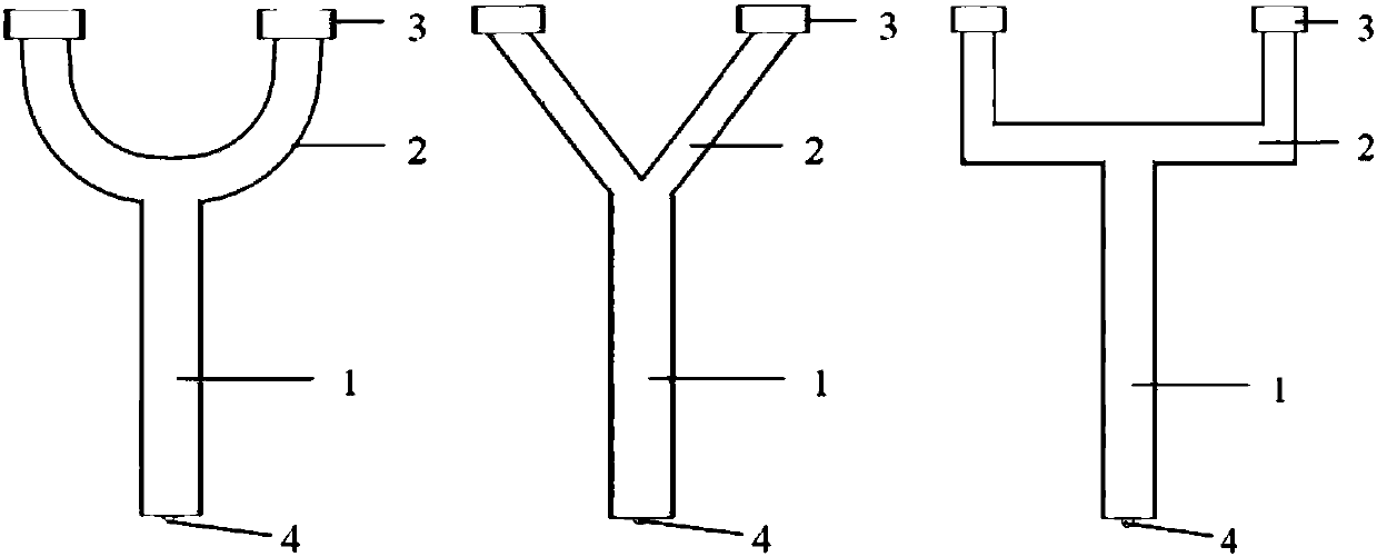
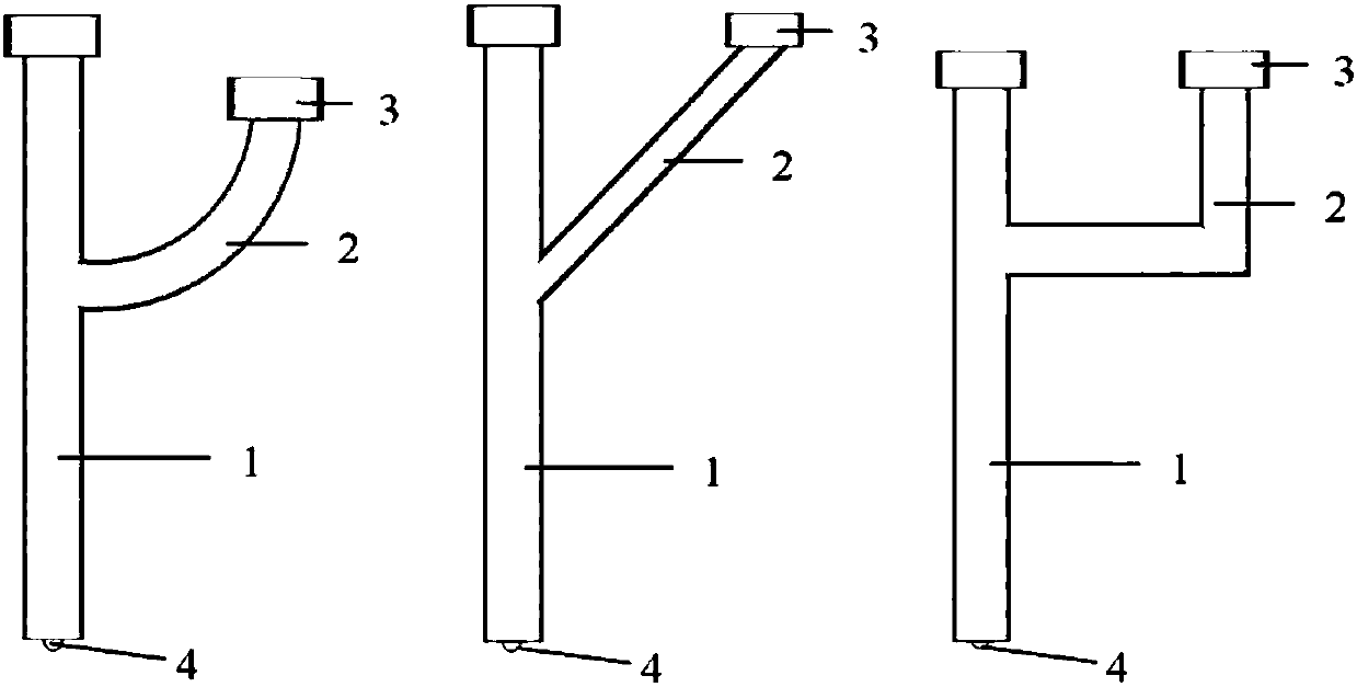
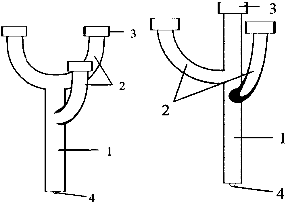
[0035] Such as Figure 1 ~ Figure 3 As shown, the branched shear connector provided by the present invention is based on the principle of bionics, and includes: a main rod 1 , a branch rod 2 , a cylinder head 3 , and an arc junction 4 . Wherein, the main rod 1 is a straight rod with a circular section, and its lower end is welded with the steel structure 5 through the arc-starting knot 4 . There are three types of branch rods 2: upper branch type, the upper end of the main rod 1 is connected with the lower end of the branch rod 2, and the branch rod 2 is a curved rod with a circular section, and its shape can be U-shaped, V-shaped, or open groove shape, etc., the upper end of the branch rod 2 is connected with the cylind...


PUM


Abstract

The invention discloses a branch-type shearing-resisting connecting part and application of the branch-type shearing-resisting connecting part in preparation of a steel-concrete composite structure. The branch-type shearing-resisting connecting part is based on the principle of bionics and comprises a main rod, a branch rod, a cylindrical head and an arc striking junction. The main rod is a circular section straight rod. The lower end of the main rod is welded to a steel structure through the arc striking junction. The upper part and / or the side surface of the main rod are / is connected with the lower end of the branch rod. The main rod and / or the upper end of the branch rod are / is connected with the cylindrical head. The diameters, geometrical sizes and connecting positions and the like ofthe main rod and the branch rod are determined according to structure stress. The branch-type shearing-resisting connecting part can effectively guarantee connection between steel and concrete, erection of steel bars is facilitated, and construction is convenient.

Description

technical field [0001] The invention belongs to the technical field of bridge engineering, and in particular relates to a branch type shear connector and its application in preparing a steel-concrete composite structure. Background technique [0002] The steel-concrete composite structure is a structure in which steel beams, connectors and reinforced concrete slabs are combined into a whole and work together. This structure combines some characteristics of steel structure and reinforced concrete structure, and has been widely used in bridge engineering. For example, the approach bridges of the Donghai Bridge, the approach bridge of the Shanghai Yangtze River Bridge, the 85m span approach bridge of the Hong Kong-Zhuhai-Macao Bridge, etc., the approach bridges of the deep-middle channel under design, and the approach bridges of the Dalian Bay Cross-sea Traffic Project have all proposed steel-concrete composite structure schemes . [0003] Steel-concrete composite structures ...

Claims


Application Information

Patent Timeline
Patent Type & Authority Applications(China)
IPC IPC(8): E01D1/00E01D101/26
Inventor 刘高张喜刚高原付佰勇王斐
Owner CCCC HIGHWAY BRIDNAT ENG RES CENT
Why Eureka
Try Eureka