Eureka AIR delivers breakthrough ideas for toughest innovation challenges, trusted by R&D personnel around the world.

Testing clamp for spring products

A technology of product testing and fixtures, which is applied in the direction of measuring devices, instruments, scientific instruments, etc., can solve problems such as difficult replacement, production waste, and impact of jaws, and achieve the effects of avoiding displacement and deformation, improving detection efficiency, and stabilizing the grip

Pending Publication Date: 2018-01-05
深圳市智诚测控技术有限公司
View PDF0 Cites 0 Cited by
  • Summary
  • Abstract
  • Description
  • Claims
  • Application Information

AI Technical Summary

Problems solved by technology

Due to the high operation accuracy requirements of spring products, the upward movement speed of spring products is too slow, resulting in too long test operation time and difficult test operation, which has caused a bottleneck in improving the production capacity of spring products.
[0005] 2. The existing fixture structure has low strength
The ordinary jaws in the original fixture are mainly aimed at grabbing lighter objects with less axial force, and the power source used is mostly pneumatic, which cannot meet the accuracy requirements. The original ordinary synchronous jaw internal gear structure is due to its structural characteristics It is easy to be damaged when the force is too large. Even if a stronger material is used, the displacement of the jaws during the test may affect the test due to the fact that the gear structure is directly stressed and it is extremely difficult to ensure the installation accuracy requirements such as the gear clearance. result
[0006] 3. Existing fixtures have poor compatibility and are not easy to replace
Existing fixtures can only be used to test a single product or 2 to 4 similar products. As a result, it is necessary to prepare a large variety of fixtures for different spring products during operation. Too many fixtures not only occupy the production space, but also cause production problems. Waste, and frequent replacement of fixtures will increase the labor intensity of operators and reduce production efficiency, which will hinder the automatic production of spring product testing

Method used


Image

  • Testing clamp for spring products
  • Testing clamp for spring products
  • Testing clamp for spring products

Examples


Embodiment Construction

[0025] The present invention will be described in detail below in conjunction with the accompanying drawings and specific embodiments.

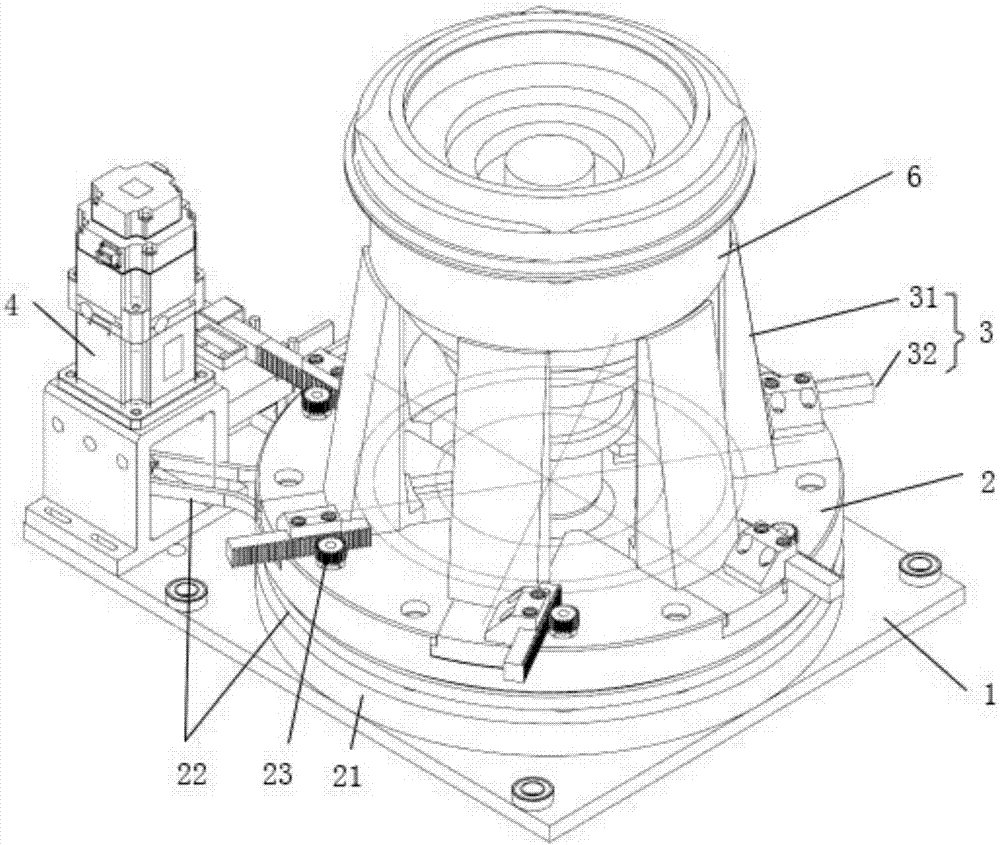
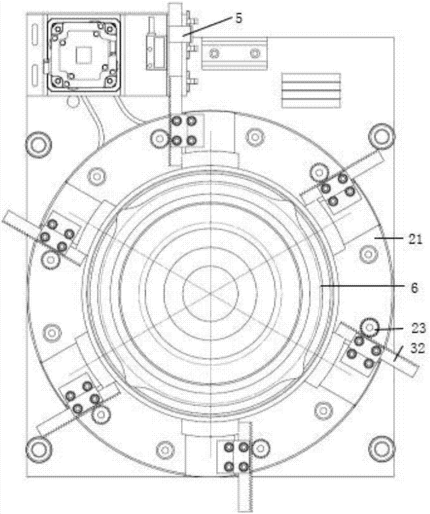
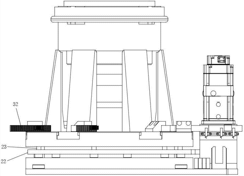
[0026] refer to figure 1 and image 3 As shown, the present invention provides a test fixture for spring products, including: a base surface 1, a transmission mechanism 2, a synchronous jaw 3 and a servo motor 4; the servo motor 4 and the transmission mechanism 2 are respectively arranged on the base surface 1; The synchronous jaw 3 is arranged on the transmission mechanism 2 and includes several claw petals 31. The claw petals 31 are distributed around the upper surface of the transmission mechanism 2 and can slide on the upper surface of the transmission mechanism 2; the servo motor 4 and The transmission mechanism 2 is connected, and the servo motor 4 drives the transmission mechanism 2 to move, thereby driving the claw valve 31 to move synchronously from the periphery of the transmission mechanism 2 to the axis of the transmission mechan...


PUM


Abstract

The invention discloses a testing clamp for spring products. The testing clamp is characterized in that the clamp comprises a base surface, a servo motor, a transmission mechanism and a synchronous clamping claw; the servo motor and the transmission mechanism are arranged on the base surface respectively; the synchronous clamping claw is arranged on the transmission mechanism and comprises a plurality of claw discs, and the claw discs are distributed on the periphery of the upper surface of the transmission mechanism and can slide on the upper surface of the transmission mechanism; the servo motor is connected with the transmission mechanism, drives the transmission mechanism to rotate, and accordingly drives the claw discs to move from the periphery of the transmission mechanism to the axis of the transmission mechanism synchronously. According to the testing clamp for the spring products, the spring products to be detected can be clamped stably and synchronously in a high-precision mode, and the situation is avoided that displacement and deformation of the clamp under the testing state cause system errors of testing; the testing clamp is compatible with multiple kinds of the spring products to be detected, quick taking and placing of the spring products to be detected are achieved, and the detection efficiency is improved.

Description

technical field [0001] The invention relates to a rigidity and tension detection fixture for spring products in the rail transit industry, in particular to a test fixture compatible with various spring products under extreme stress. Background technique [0002] Spring products are widely used in the rail transit industry. They are mainly used for shock absorption and mechanism connection of high-speed rail transit vehicles, and they need to withstand great pressure and impact. Due to the functional characteristics of spring products, there are extremely high requirements for the quality inspection of spring products. Spring products are made of vulcanized metal parts and rubber parts, which are multi-layer cylindrical structures. In the test, it is necessary to test the rigidity and tensile properties of the front and back sides of the corresponding spring products to check whether the adhesion between the rubber material and the metal material meets the standard. [0003...

Claims


Application Information

Patent Timeline
IPC IPC(8): G01N3/04
Inventor 邹其超
Owner 深圳市智诚测控技术有限公司
Why Eureka
Eureka Blog
Learn More