A patch antenna structure, antenna feeder board and base station transceiver

A base station transceiver and patch antenna technology, applied in the direction of antenna grounding switch structure connection, antenna grounding device, radiation element structure, etc., can solve the problems of increasing antenna height, deteriorating port isolation and cross polarization, etc., to achieve Reduce the height, optimize the structure of the whole machine, and eliminate the effect of excessive product volume

Active Publication Date: 2020-11-06
SHENZHEN SAMSUNG COMM TECH RES +1
View PDF7 Cites 0 Cited by
  • Summary
  • Abstract
  • Description
  • Claims
  • Application Information

AI Technical Summary

Problems solved by technology

In this way, a certain gap must be left between the antenna and the radome, which objectively increases the height of the antenna.
[0004] In addition, although artificial magnetic conductor technology exists that can reduce the height of the base station antenna, this technology can only be used under narrowband conditions, and in dual polarization applications, there may be side effects of degraded port isolation and cross polarization

Method used


Image

  • A patch antenna structure, antenna feeder board and base station transceiver
  • A patch antenna structure, antenna feeder board and base station transceiver
  • A patch antenna structure, antenna feeder board and base station transceiver

Examples


Embodiment Construction

[0021] The following will clearly and completely describe the technical solutions in the embodiments of the present invention with reference to the accompanying drawings in the embodiments of the present invention. Obviously, the described embodiments are only some, not all, embodiments of the present invention. Based on the embodiments of the present invention, all other embodiments obtained by persons of ordinary skill in the art without creative efforts fall within the protection scope of the present invention.

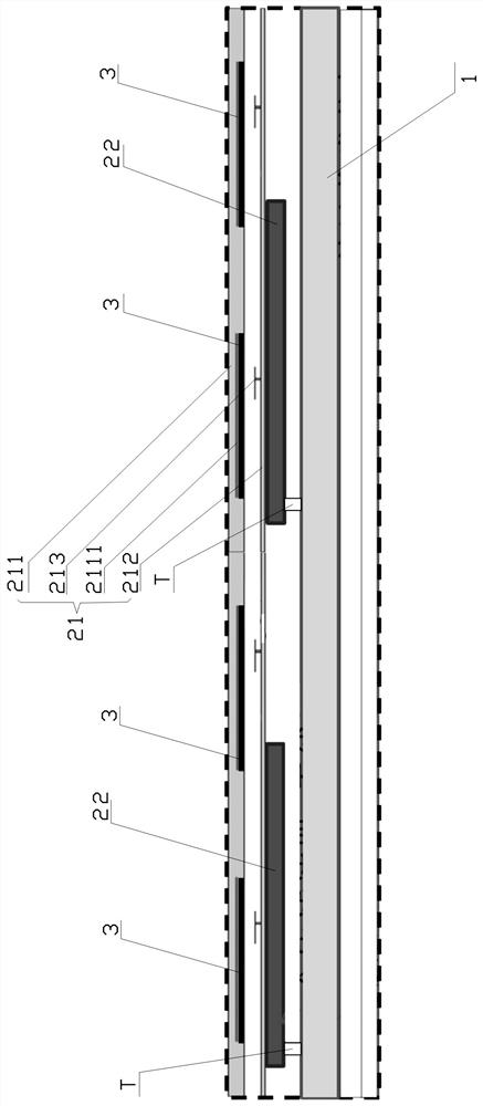
[0022] see figure 1 , is Embodiment 1 of the base transceiver station of the present invention.

[0023] In the present embodiment, the base station transceiver includes: a radio frequency digital assembly 1 and an antenna filter assembly connected to one side of the radio frequency digital assembly 1, and the antenna filter assembly includes: an antenna feeder board 21 keeping a certain distance from the radio frequency digital assembly 1; The dielectric filter 2...


PUM


Abstract

The invention discloses a patch antenna structure. The patch antenna structure comprises an antenna cover, a metal floor and an antenna radiation patch, wherein the metal floor is arranged at one sideof the antenna cover and is kept away from the antenna cover with a certain distance, a feeding patch is connected to a side wall of one side, facing the antenna cover, of the metal floor, the antenna radiation patch is pasted on a side wall of one side, facing the metal floor, of the antenna cover, and the certain distance is kept between the antenna radiation patch and the metal floor so as tomaintain radio frequency characteristic of the patch antenna. The invention also discloses a base station transceiver and an antenna feeder plate. By implementing the patch antenna structure, the antenna feeder plate and the base station transceiver, the height of the antenna is reduced on the premise of ensuring antenna bandwidth, the structure of the whole machine is optimized, and the volume ofa product is reduced.

Description

technical field [0001] The invention relates to the field of communication equipment, in particular to a patch antenna structure, an antenna feeder board and a base station transceiver. Background technique [0002] In the prior art, base station antenna designs such as antenna feeder boards and base station transceivers have the following technical defects due to unreasonable structures, such as: [0003] Most of the existing base station antenna designs are separate, that is, the antenna is designed and processed separately, and then assembled with the radome. In this way, a certain gap must be reserved between the antenna and the radome, which objectively increases the height of the antenna. [0004] In addition, although artificial magnetic conductor technology exists that can reduce the height of the base station antenna, this technology can only be used under narrowband conditions, and in dual-polarization applications, there may be side effects of degraded port isola...

Claims


Application Information

Patent Timeline
Patent Type & Authority Patents(China)
IPC IPC(8): H01Q1/38H01Q1/42H01Q1/48H01Q1/50H04B1/40
Inventor 靳炉魁蔡磊牛兵建
Owner SHENZHEN SAMSUNG COMM TECH RES
Why Eureka
Try Eureka