Motor, activation control method for motor, and fan including motor

A motor and fan technology, applied in the direction of electronic commutation motor control, program control, control system, etc., can solve the problems of the motor starting not smoothly, starting dead angle, unable to automatically adjust the starting force, etc., so as to improve the starting smoothness and reduce the complexity. degree and cost

Inactive Publication Date: 2018-01-05
SUNONWEALTH ELECTRIC MACHINE IND
View PDF6 Cites 0 Cited by
  • Summary
  • Abstract
  • Description
  • Claims
  • Application Information

AI Technical Summary

Problems solved by technology

Among them, with the different electric devices used by the motor, the loads (such as fan blades) that the driver needs to drive are also different, and the power output by the rotor of the motor must match the load. If the power is too large, it will easily cause the electric device to vibrate; if If the power is too small, it is not enough to drive the load
[0004] However, the existing motor start-up control method is only suitable for a fixed load, and cannot automatically adjust the start-up force to adapt to the difference in quality. Therefore, when the motor is started, it is very easy to cause the electric device to repeatedly seek angles due to factors such as power mismatch or start-up dead angle. , starting for too long or failure to start, etc., causing the motor to not start smoothly

Method used


Image

  • Motor, activation control method for motor, and fan including motor
  • Motor, activation control method for motor, and fan including motor
  • Motor, activation control method for motor, and fan including motor

Examples


Embodiment Construction

[0026] In order to make the above and other purposes, features and advantages of the present invention more comprehensible, the preferred embodiments of the present invention are specifically cited below, together with the accompanying drawings, as follows:

[0027] Directional terms such as "front", "rear", "left", "right", "upper (top)", "lower (bottom)", "inner", "outer", " "side" and so on are mainly referring to the directions of the accompanying drawings, and the directional terms are only used to assist in explaining and understanding various embodiments of the present invention, and are not intended to limit the present invention.

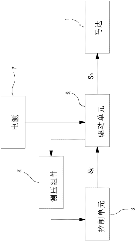
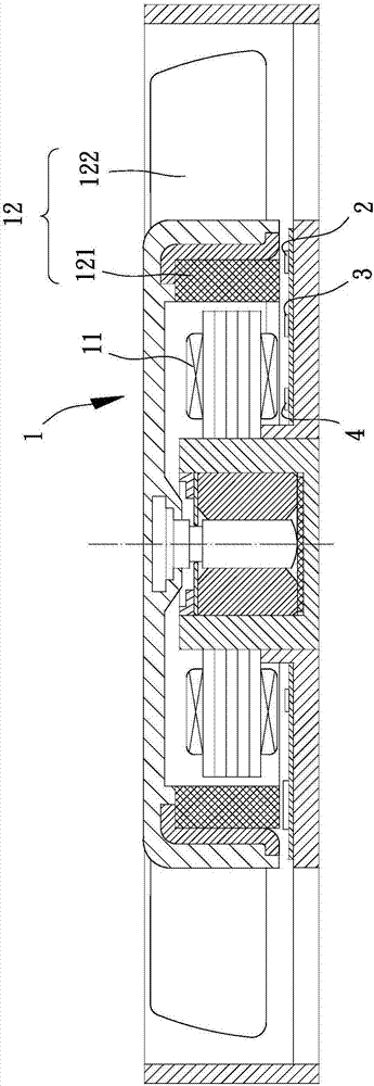
[0028] see figure 1 and figure 2 As shown, it is a schematic block diagram and a combined cross-sectional view of a motor embodiment of the present invention applied to a fan. Wherein, the motor 1 can be used as a power output source of a fan or other electric devices. Taking a fan as an example, the fan can include: the motor 1 and a dr...


PUM


Abstract

The invention mainly provides a motor, an activation control method for the motor, and a fan including the motor to solve the problem of the prior art that motor activation strength cannot be adjustedautomatically due to differences of loads. The motor includes a stator coil, a rotor and a driving unit. The stator coil is configured to be electrified to generate a magnetic force. The rotor is rotatably coupled with the stator coil and includes a magnetic member facing the stator coil. The driving unit is electrically connected to the stator coil and outputs a driving signal to the stator coil. An electrical characteristic value of the driving signal increases in a gradual manner. The rotor outputs a motive power that is gradually increased during a process the rotor rotates from an electric angle back to a same electric angle. Therefore, the problem of the prior art can be solved.

Description

technical field [0001] The invention relates to a motor, its starting control method and a fan with the motor, in particular to a motor capable of automatically adjusting the starting force to adapt to different loads, its starting control method and the fan with the motor. Background technique [0002] The motor can convert electric power into power output, which is used to drive a load to form various electric devices. Taking the fan as an example, the existing fan can use the motor to convert electric energy into power output, so that the motor can drive the blades to generate airflow, which can be used for air circulation or heat dissipation. The shape of the fan can be wall fan, ceiling fan, Blower fan or axial fan, etc. [0003] When the conventional motor is to be started, a general driver can output a driving signal to the coil of the motor to drive the rotor of the motor to start rotating. Among them, with the different electric devices used by the motor, the load...

Claims


Application Information

Patent Timeline
Patent Type & Authority Applications(China)
IPC IPC(8): H02P1/16F04D25/08
CPCG05B19/042H02P6/157H02P6/21Y02B90/20Y04S40/121G05B19/0423H02J13/00009H05B47/16
Inventor 洪银树邱智翔
Owner SUNONWEALTH ELECTRIC MACHINE IND
Why Eureka
Try Eureka