
Method and device for optical fiber transmission

An optical fiber transmission and optical power technology, applied in the field of communications, can solve the problems of unstable output, uncontrollable noise, and inability to adjust in real time, and achieve the effects of stable transmission, low noise, and controllable output results

Active Publication Date: 2021-11-16
ZTE CORP
View PDF4 Cites 0 Cited by
  • Summary
  • Abstract
  • Description
  • Claims
  • Application Information

AI Technical Summary

Problems solved by technology

[0004] The purpose of the embodiments of the present invention is to provide a method for optical fiber transmission, which solves the problem that in optical fiber transmission, the gain of the optical power for amplifying the optical signal can only be preset, and cannot be adjusted in real time, resulting in uncontrollable noise during optical signal transmission and inconsistent output. stability problem

Method used


Image

  • Method and device for optical fiber transmission
  • Method and device for optical fiber transmission
  • Method and device for optical fiber transmission

Examples


Embodiment Construction

[0019] In order to make the technical problems, technical solutions and advantages to be solved by the present invention clearer, the following will describe in detail with reference to the drawings and specific embodiments.

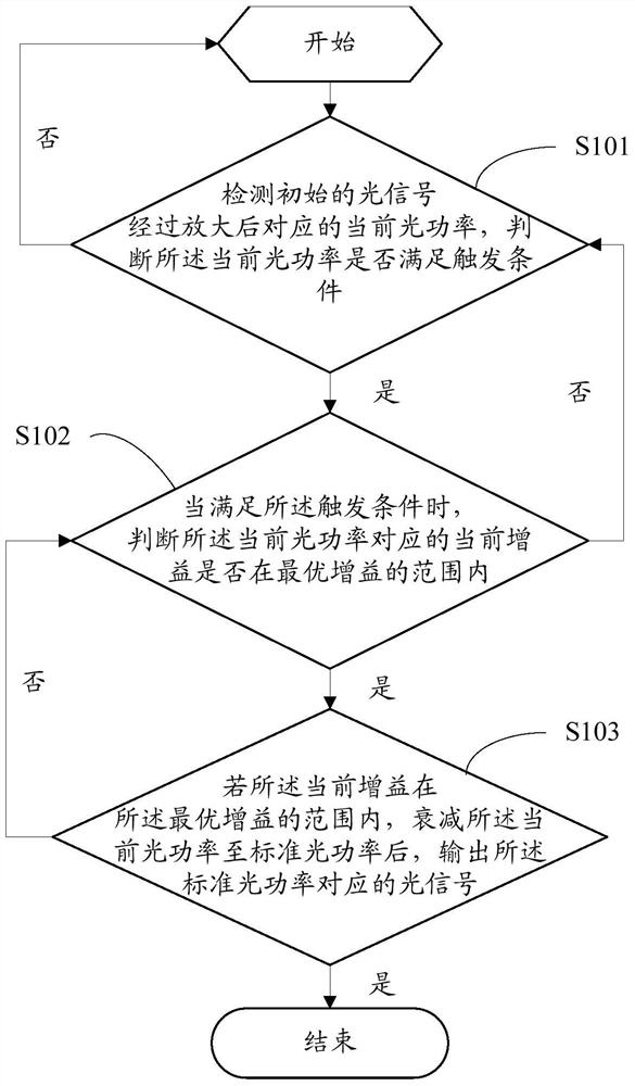
[0020] Such as figure 1 As shown, the embodiment of the present invention provides a method for optical fiber transmission, including the following steps:

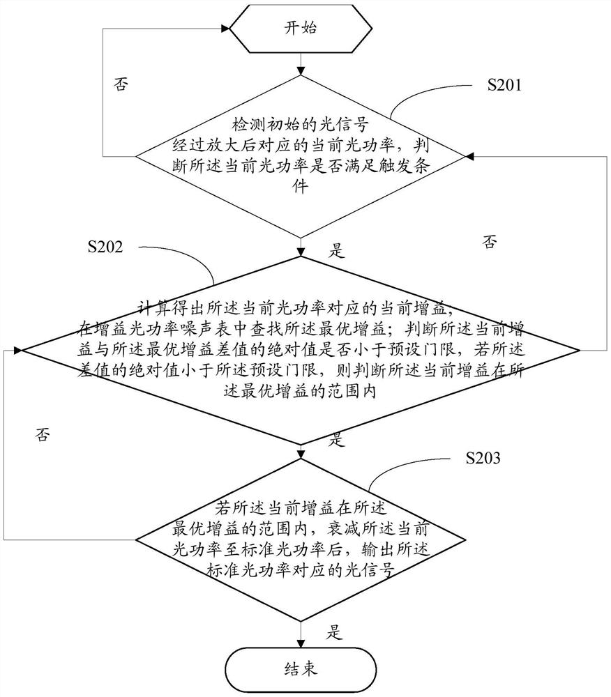
[0021] Step S101, detecting the current optical power corresponding to the initial optical signal after amplification, and judging whether the current optical power satisfies a trigger condition, wherein the trigger condition is that the current optical power is greater than or equal to the initial optical power of the optical signal and the The sum of the preset gains of the above-mentioned initial optical power.

[0022] In this step, first start the optical fiber transmission system and set the initial parameters. The initial parameters can include the initial optical power of the optical signal,...


PUM


Abstract

The present invention provides a method and device for optical fiber transmission, including: detecting the current optical power corresponding to the amplified initial optical signal, judging whether the current optical power satisfies a trigger condition, and judging whether the current optical power satisfies the trigger condition Whether the current gain corresponding to the optical power is within the range of the optimal gain, if the current gain is within the range of the optimal gain, after attenuating the current optical power to the standard optical power, output the An optical signal, wherein the standard optical power is a standard value after the initial power is amplified by the preset gain. In this way, the optical power value and gain of the optical signal in the optical fiber transmission can be controlled in real time to adjust to the best optical power value and gain, the transmission is stable, and the noise is low. Finally, the amplified optical signal is attenuated to meet the requirements of the user. The signal gain value is required, and the output result is controllable.

Description

technical field [0001] The invention relates to the technical field of communication, in particular to a method and device for optical fiber transmission. Background technique [0002] With the advancement of society, the application of optical fiber communication technology has grown rapidly. Since the first commercial installation of the optical fiber system in 1977, telephone companies have begun to use optical fiber links to replace the old copper wire system. Optical fiber transmission, that is, data and signal transmission using optical fiber as the medium. Optical fibers can not only be used to transmit analog and digital signals, but also meet the needs of video transmission. Optical fiber is a very convenient tool for signal transmission. A slender optical core in the cable can replace more than a thousand physical communication lines to complete a large number of long-distance communication tasks. [0003] Although optical fiber transmission has the advantages of...

Claims


Application Information

Patent Timeline
Patent Type & Authority Patents(China)
IPC IPC(8): H04B10/25H04B10/291H04B10/293
Inventor 白林波
Owner ZTE CORP
Learn More