
Physical layer transmission parameter configuration and acquisition method and device

A technology of transmission parameters and configuration methods, which is applied in the field of communication and can solve problems such as inflexible configuration of physical layer transmission parameters

Inactive Publication Date: 2018-01-05
ZTE CORP
View PDF2 Cites 9 Cited by
  • Summary
  • Abstract
  • Description
  • Claims
  • Application Information

AI Technical Summary

Problems solved by technology

[0009] The embodiment of the present invention provides a physical layer transmission parameter configuration, acquisition method and device, to at least solve the problem in the related art that the first type of physical layer transmission parameters cannot be flexibly configured

Method used


Image

  • Physical layer transmission parameter configuration and acquisition method and device
  • Physical layer transmission parameter configuration and acquisition method and device
  • Physical layer transmission parameter configuration and acquisition method and device

Examples


Embodiment 1

[0330] In the design of 5G new air interface, due to different services and different moving speeds, the base station can no longer define the physical layer time interval unit from the level of the entire cell; in order to improve flexibility, the physical layer time interval unit in the time domain The length is variable, and the indication information of the physical layer time interval unit length can be notified on the physical layer broadcast (or multicast) channel, Figure 8 is a schematic diagram of physical layer broadcast or multicast channel transmission in related technologies, such as Figure 8 as shown,

[0331] The signaling of the physical layer broadcast (or multicast) channel can configure the physical layer time interval unit of the physical layer broadcast (or multicast) channel (e.g the time slot, the subframe, or the wireless half frame, or the wireless frame) physical layer time interval unit length; there are many optional configurations, for example, ...

Embodiment 2

[0350] In Embodiment 1, the configuration parameter information of the physical layer time interval unit may also be boundary indication information of the physical layer time interval unit; here, the physical layer time interval unit boundary indication information has the following typical types.

[0351] Slot / subframe boundaries:

[0352] When the synchronization is completed and the physical layer broadcast (or multicast) channel is detected, the current time slot / subframe start position can be indicated, such as x symbols before the synchronization signal, and the end position is the physical layer broadcast (or multicast ) the yth symbol after the last symbol of the channel; x, y are natural numbers; absolute time indication can also be used, such as X ms before the synchronization signal, and the end position is the last one of the physical layer broadcast (or multicast) channel Y ms after the symbol; belongs to the subframe and time slot;

[0353] Figure 12 It is a ...

Embodiment 3

[0358] In Embodiment 1, it is considered that the transmission channel signal of the physical layer is defined based on one physical layer time interval unit. The embodiment of the present invention also supports the aggregation of multiple physical layer time interval units to define the transmission of the physical layer. channel signal condition, Figure 13 It is a schematic diagram of physical layer broadcast or multicast channel transmission according to an embodiment of the present invention Figure five ,Such as Figure 13 As shown, the aggregation parameter indication of the time interval unit; the aggregation parameter indication of the time interval unit at the resource group level is also supported.

[0359] The notification method is similar to Embodiment 1. The transmission of the physical layer broadcast (or multicast) channel can also be bound with multiple resource groups, and there can be multiple aggregation parameters for multiple physical layer time interv...


PUM


Abstract

The invention provides a physical layer transmission parameter configuration and acquisition method and device. The physical layer transmission parameter configuration method comprises the following steps: dividing transmission resources into N resource groups, wherein N is greater than or equal to 1; determining a first class of physical layer transmission parameters, which include at least one of the following: definition indication information of a base resource unit, aggregation indication information of a physical layer time interval unit, basic transmission structure configuration parameter information, and Numerology parameter configuration information; mapping indication information of a channel signal, mode indication information of resource allocation, frequency domain availablebandwidth indication information of a resource group, transmission power indication information of resources, and measurement pilot configuration information; and informing the receiving end of the first class of physical layer transmission parameters corresponding to the N resource groups. The physical layer transmission parameter configuration method provided by the invention solves the problemthat the first class of physical layer transmission parameters cannot be configured flexibly in the related technology, and different UE can be flexibly configured.

Description

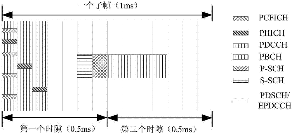
technical field [0001] The present invention relates to the communication field, in particular, to a method and device for configuring and acquiring physical layer transmission parameters. Background technique [0002] In wireless communication, it is generally necessary to define multiple types of physical layer time interval (Time Interval) units, and define channel signal mapping and resource scheduling based on these physical layer time interval units. These physical layer time interval units can be defined by a fixed duration, or by multiple time-domain symbols; taking the 4G wireless communication system Long Term Evolution (LTE for short) as an example, in the time domain, LTE defines several types of physical layer time interval units, and fixes and describes the frame structure for these physical layer time interval units. figure 1 is a schematic diagram of the frame structure of the FDD system in the related art, such as figure 1 As shown, a radio frame (Radio Fr...

Claims


Application Information

Patent Timeline
Patent Type & Authority Applications(China)
IPC IPC(8): H04L5/00H04L5/02
CPCH04L5/00H04L5/0007H04L5/0053H04W72/23H04W72/30H04L5/0032
Inventor 陈艺戬鲁照华李儒岳吴昊
Owner ZTE CORP
Learn More