Traffic forwarding method, device and system

A traffic forwarding and flow technology, applied in the field of network communication, can solve the problems of high IPL link bandwidth requirements and increased IPL link business burden, so as to improve forwarding reliability, reduce IPL link burden, and reduce business messages the lost effect of

Active Publication Date: 2018-01-05
NEW H3C TECH CO LTD
View PDF4 Cites 20 Cited by
  • Summary
  • Abstract
  • Description
  • Claims
  • Application Information

AI Technical Summary

Problems solved by technology

[0006] Currently, when the DR interface of a member device used to forward traffic in a distributed aggregation DR group fails, the traffic to be forwarded will be forwarded to the neighboring

Method used


Image

  • Traffic forwarding method, device and system
  • Traffic forwarding method, device and system
  • Traffic forwarding method, device and system

Examples


Example

[0159] Example 1

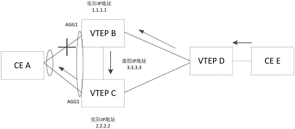
[0160] Such as Figure 3a As shown, the DR group includes two member devices VTEP B and VTEP C. VTEP B and VTEP C are connected to a customer edge CE device CE A (traffic receiving device) through a distributed aggregated DR port. CE A is connected to CE A through two physical ports. Aggregate DR port connection. The actual IP addresses on VTEP B and VTEP C are 1.1.1.1 and 2.2.2.2 respectively, and VTEP B and VTEP C record the actual IP address and DR port status of their respective peer member devices, that is, the record address of VTEP B is 2.2. 2.2 and DR port status is UP, VTEP C record address is 1.1.1.1 and DR port status is DOWN. When the DR port states of VTEP B and VTEP C are both UP, VTEP B and VTEP C advertise the virtual IP address 3.3.3.3, and the DR group establishes the VXLAN tunnel tunnel0 between the DR group and VTEP D through the virtual IP address. , To communicate with the flow sending device (VTEP D).

[0161] When VTEP B detects that th...

Example

[0174] Example 2

[0175] Such as Figure 3c As shown, the DR group includes four member devices VTEP B, VTEP C, VTEP E, and VTEP F. VTEP B, VTEP C, VTEP E, and VTEP F are connected to the user edge CE device CE A ( Traffic receiving equipment), CE A is connected to the aggregated DR port through four physical ports. The DR port status of each member device is initially UP. Each member device in the DR group records the actual IP address and DR port status of each member device. For example, VTEP B records VTEP B, VTEP C, VTEP E, and VTEP F corresponding to The actual IP address and DR port status.

[0176] The actual IP address on VTEP B is 1.1.1.1, the actual IP address on VTEP C is 2.2.2.2, the actual IP address on VTEP E is 1.1.1.2, the actual IP address on VTEP F is 2.1.1.1, and the actual IP address on VTEP B is 2.1.1.1. , VTEP C, VTEP E, VTEPF four devices all advertise the virtual IP address 3.3.3.3, the DR group establishes the VXLAN tunnel tunnel0 between the DR group a...


PUM


Abstract

The invention discloses a traffic forwarding method, device and system. The method includes the following steps that when a link, connected with a traffic receiving device, of a member device breaks down, a first synchronous message including DR port fault states of the member device is sent to other member devices in a DR group, and the first synchronous message is used for informing the other member devices of the DR port states of the member device; the member devices which do not break down in the DR group are determined, agent member devices used for traffic forwarding are determined fromthe member devices which do not break down, and according to the actual IP addresses of the agent member devices, a first route is generated; traffic sending equipment is informed of the first route,the first route is used for the DR port states of the member device, and the traffic sending equipment is used for forwarding the traffic forwarded by the member device through a tunnel between the traffic sending equipment and the agent member device. According to the traffic forwarding method and the device, the situation that the IPL chain causes loss of the service messages because of bandwidth deficiency is reduced, and the forwarding reliability is improved.

Description

technical field [0001] The present disclosure relates to the technical field of network communication, and in particular to a traffic forwarding method, device and system. Background technique [0002] In order to improve the high reliability of the network, a distributed aggregation scheme is usually adopted. The basic idea of ​​the distributed aggregation scheme is to allow multiple access devices to perform link aggregation negotiation with the connected device in the same state. From the perspective of the incoming device, it is as if a link aggregation relationship has been established with a device. [0003] Distributed aggregation has two basic concepts, IPP port and DR port. [0004] Wherein, an IPP (Intra-Portal Port, internal control link port) port refers to a Layer 2 aggregation interface used for internal control by connecting to neighboring member devices of the DR group. Each DR member device has only one IPP port, and the IPP ports of the DR member devices ...

Claims


Application Information

Patent Timeline
IPC IPC(8): H04L12/703H04L12/741H04L29/08H04L45/28H04L45/74
Inventor 唐成黄李伟
Owner NEW H3C TECH CO LTD
Why Eureka
Try Eureka