Vibrating sieve device for combine harvester

A technology of combine harvester and vibrating device, which is applied in agricultural machinery and implements, threshing equipment, applications, etc., can solve the problems of inability to realize screen replacement, inconvenient screening of material discharge, etc., and achieve convenient screen replacement, rapid screening, good filtering effect

Inactive Publication Date: 2018-01-09
安徽诺鑫自动化设备有限公司
6 Cites 1 Cited by

AI-Extracted Technical Summary

Problems solved by technology

[0004] However, when the device is used for vibration screening, the replacement of th...

Abstract

The invention discloses a vibrating sieve device of a combine harvester. The vibrating sieve device includes a support frame, a screening net, a vibrating device, a discharging device and a feeding hopper; the screening net is fixed through a metal frame on the surface, an annular groove is formed in the side face of the metal frame, and the screening net is fixed inside the metal frame through the groove; the vibrating device comprises a vibrating motor and a hydraulic rod, the vibrating motor is arranged at the bottom end of the metal frame, hinged bases are arranged at corners of the bottomend of the metal frame, and the metal frame is connected together with the hydraulic rod through the hinged bases in a hinged mode; the discharging device comprises a first discharging plate and a second discharging plate, the first discharging plate is connected with one end of a screening chamber, and the second discharging plate is connected with one end of a discharging chamber. According tothe vibrating sieve device of the combine harvester, quick screening of materials is achieved through dual vibration, the materials after screening can be quickly classified and discharged, meanwhilereplacement of the screening net is convenient, the screening effect is good, and the vibrating sieve device is worth popularizing.

Application Domain

Threshers

Technology Topic

SieveCombine harvester +2

Image

  • Vibrating sieve device for combine harvester
  • Vibrating sieve device for combine harvester
  • Vibrating sieve device for combine harvester

Examples

  • Experimental program(1)

Example Embodiment

[0020] Examples:
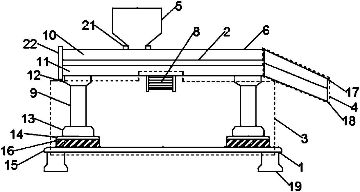
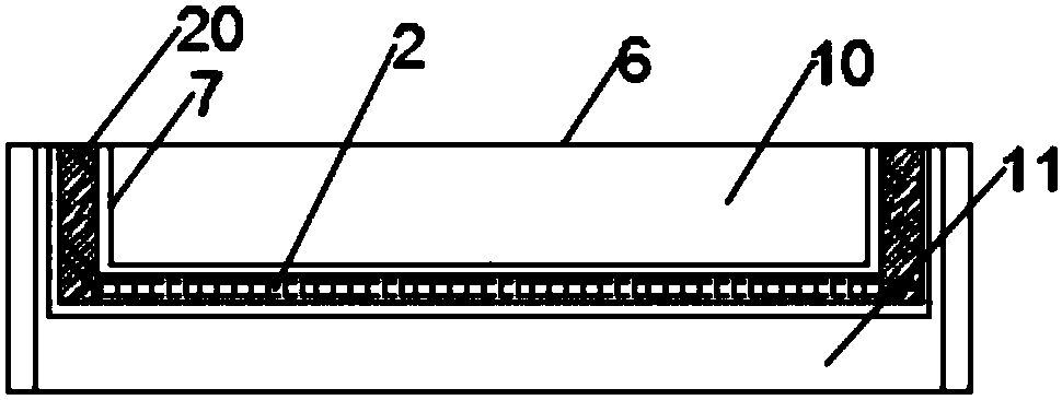
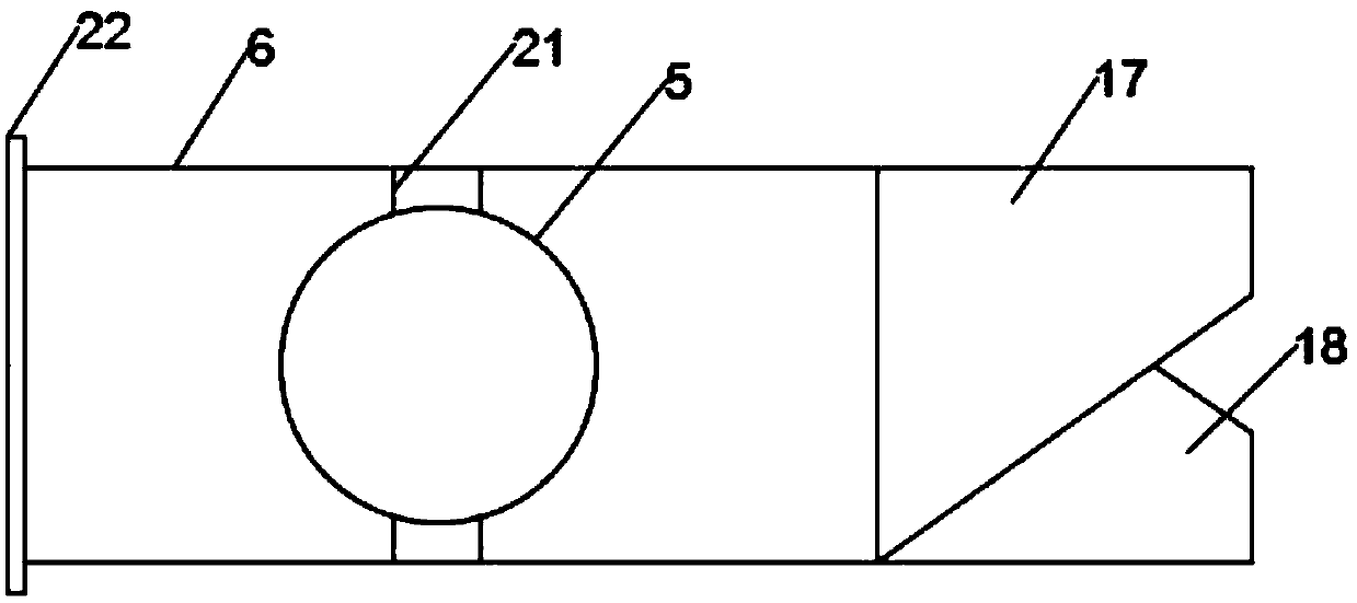
[0021] Such as figure 1 , figure 2 with image 3 As shown, the present invention proposes a technical solution: a vibrating screen device for a combine harvester, including a support frame 1, a screen 2, a vibrating device 3, a discharging device 4, and a hopper 5 through which the screen 2 passes The metal frame 6 on the surface is fixed, the side of the metal frame 6 is provided with an annular groove 7, the screen 2 is fixed inside the metal frame 6 through the groove 7, and the screen 2 divides the inside of the metal frame 6 into The screening chamber 10 and the discharging chamber 11 are located above the discharging chamber 11. The vibrating device 3 includes a vibrating motor 8 and a hydraulic rod 9. The vibrating motor 8 is installed at the bottom end of the metal frame 6, so A hinge seat 12 is installed at the bottom corners of the metal frame 6. The metal frame 6 is hingedly connected with the hydraulic rod 9 through the hinge seat 12, and the hydraulic rod 9 is driven by a hydraulic motor 13. The hydraulic motor 13 is fixed by a motor base 14. The motor base 14 is fixedly installed on the surface of the base 15. At the same time, when the hydraulic rods 9 at both ends are at different heights, gravity can facilitate the discharge of materials; the bottom end of the motor base 14 A shock-absorbing spring 16 is provided. The discharging device 4 includes a first discharging disc 17 and a second discharging disc 18. The first discharging disc 17 and one end of the screening chamber 10 are connected together, and the second outlet The material tray 18 and one end of the discharge chamber 11 are connected together, and the openings of the first discharge tray 17 and the second discharge tray 18 face the same.
[0022] The support frame 1 is composed of a number of support rods 19, the support rods 19 and the shock-absorbing spring 16 are connected together; the screen 2 is made of high manganese steel; both ends of the screen 2 are vertically connected with metal The metal plates 20 are parallel to each other, and the two sides of the metal plate 20 and the groove 7 are the same size. The screen 2 is fixedly installed by the clamping of the metal plate 20 and the groove 7. 2 One end is connected with a blocking plate 22, which is restricted by the blocking plate 22 to prevent materials from escaping from one end of the screen 2; the upper surfaces of the first and second discharge trays are parallel to each other, and the first discharge tray The upper surface of the tray and the upper surface of the metal frame are at an angle of 150°-170° to facilitate the discharge of materials; a connecting frame 21 is installed at the top of the metal frame 6, and the feeding hopper 5 is fixed by the connecting frame 21.
[0023] Specific implementation and advantages: The vibrating screen device of the combine harvester is equipped with a vibrating device, using a vibrating motor to directly vibrate the metal frame, and directly vibrate the screen through the vibration effect to complete the first-level vibration screening, and pass Set up the hydraulic rod and use the hydraulic motor to realize the back and forth movement of the hydraulic rod. The vibration of the metal frame and the screen can be realized by the up and down movement of the hydraulic rod, thus completing the secondary vibration screening, and achieving the screening through double vibration, which speeds up the screening process. At the same time, by setting grooves, the screen is fixed and installed by the grooves, which is convenient for disassembly of the screen. At the same time, after screening, the materials in the screening chamber and the discharging chamber are discharged through the first discharge tray and the second discharge tray respectively. , It can realize the classification and discharge of materials and complete the vibration screening. The device realizes the rapid screening of materials through double vibration, and the materials after screening can be quickly classified and discharged. At the same time, it is convenient to replace the screen. The screening effect is good and it is worthy of promotion.

PUM

no PUM

Description & Claims & Application Information

We can also present the details of the Description, Claims and Application information to help users get a comprehensive understanding of the technical details of the patent, such as background art, summary of invention, brief description of drawings, description of embodiments, and other original content. On the other hand, users can also determine the specific scope of protection of the technology through the list of claims; as well as understand the changes in the life cycle of the technology with the presentation of the patent timeline. Login to view more.

Similar technology patents

Method for measuring particle size distribution of particles, and apparatus thereof

InactiveCN103983546Aacceleratelower requirement
Owner:INST OF HIGH ENERGY PHYSICS CHINESE ACADEMY OF SCI

Current based open-circuit fault detection method for three-phase inverter

InactiveCN104597368AThe overall calculation is smallaccelerate
Owner:UNIV OF ELECTRONIC SCI & TECH OF CHINA

Concrete building block cutting device

Owner:ZHEJIANG DADONGWU GROUP CONSTR OF THE NEW MATERIAL

Classification and recommendation of technical efficacy words

  • accelerate
  • Easy to disassemble

Three-dimensional circuit manufacturing process and composite components of laser plastic material and manufacturing method

ActiveCN101859613Aaccelerateaccelerated continuous motion
Owner:深圳市微航磁电技术有限公司

Failure recognition method and system based on neural network self-learning

ActiveCN103914735ASpeed ​​up fault identificationaccelerate
Owner:BEIJING TAILEDE INFORMATION TECH

Novel ceiling mounting structure

Owner:上海西蒙铝业有限公司

Inspection robot for underground coal mine

Owner:安徽玄离智能科技股份有限公司

Multistep assemblied anti-settle magnetic rheological damper

InactiveCN1869470AEasy to disassembleSimple processing design
Owner:TIANJIN UNIV
Why Eureka
Try Eureka