Eureka AIR delivers breakthrough ideas for toughest innovation challenges, trusted by R&D personnel around the world.

Mixed stirring and sieving device of fodder

A technology of mixing, stirring and screening devices, which is applied in the direction of feed, mixers, mixers with rotating stirring devices, etc., can solve the problems of high labor intensity, uneven particle size of feed powder, and affecting animal growth and development. Stirring area, the effect of improving transmission and mixing efficiency

Inactive Publication Date: 2018-01-09
高明飞
View PDF5 Cites 2 Cited by
  • Summary
  • Abstract
  • Description
  • Claims
  • Application Information

AI Technical Summary

Problems solved by technology

[0002] At present, in the breeding of poultry and livestock, the size of the feed powder particles is not uniform due to the insufficient production of the feed, and the feed is often screened and processed twice; to strictly ensure the uniformity of the size of the feed product, it is necessary to use a screening device for processing , in order to meet the qualified requirements; sometimes it is necessary to mix a variety of feeds together, and whether the feed is mixed uniformly will also affect the growth and development of animals; traditional feed screening methods can be roughly divided into manual screening and mechanical screening methods; manual screening, mainly It is to rely on manual use of sieves to select granular materials. This method is labor-intensive and the production efficiency is not high; mechanical screening is often used with complex structure material screening machines. Although the efficiency is high, the mechanical structure is complicated and takes up a lot of space. It is not suitable for screening tasks with different processing volumes; therefore, it is particularly important to develop a feed screening device with a simple structure and a uniform mixing function

Method used


Image

  • Mixed stirring and sieving device of fodder
  • Mixed stirring and sieving device of fodder
  • Mixed stirring and sieving device of fodder

Examples


Embodiment Construction

[0016] The technical solution of this patent will be further described in detail below in conjunction with specific embodiments.

[0017] Embodiments of the present patent are described in detail below, examples of which are shown in the drawings, wherein the same or similar reference numerals designate the same or similar elements or elements having the same or similar functions throughout. The embodiments described below by referring to the figures are exemplary and are only used for explaining the patent, and should not be construed as limiting the patent.

[0018] In the description of this patent, it is to be understood that the terms "center", "upper", "lower", "front", "rear", "left", "right", "vertical", "horizontal", The orientation or positional relationship indicated by "top", "bottom", "inner", "outer", etc. is based on the orientation or positional relationship shown in the drawings, and is only for the convenience of describing this patent and simplifying the des...


PUM


Abstract

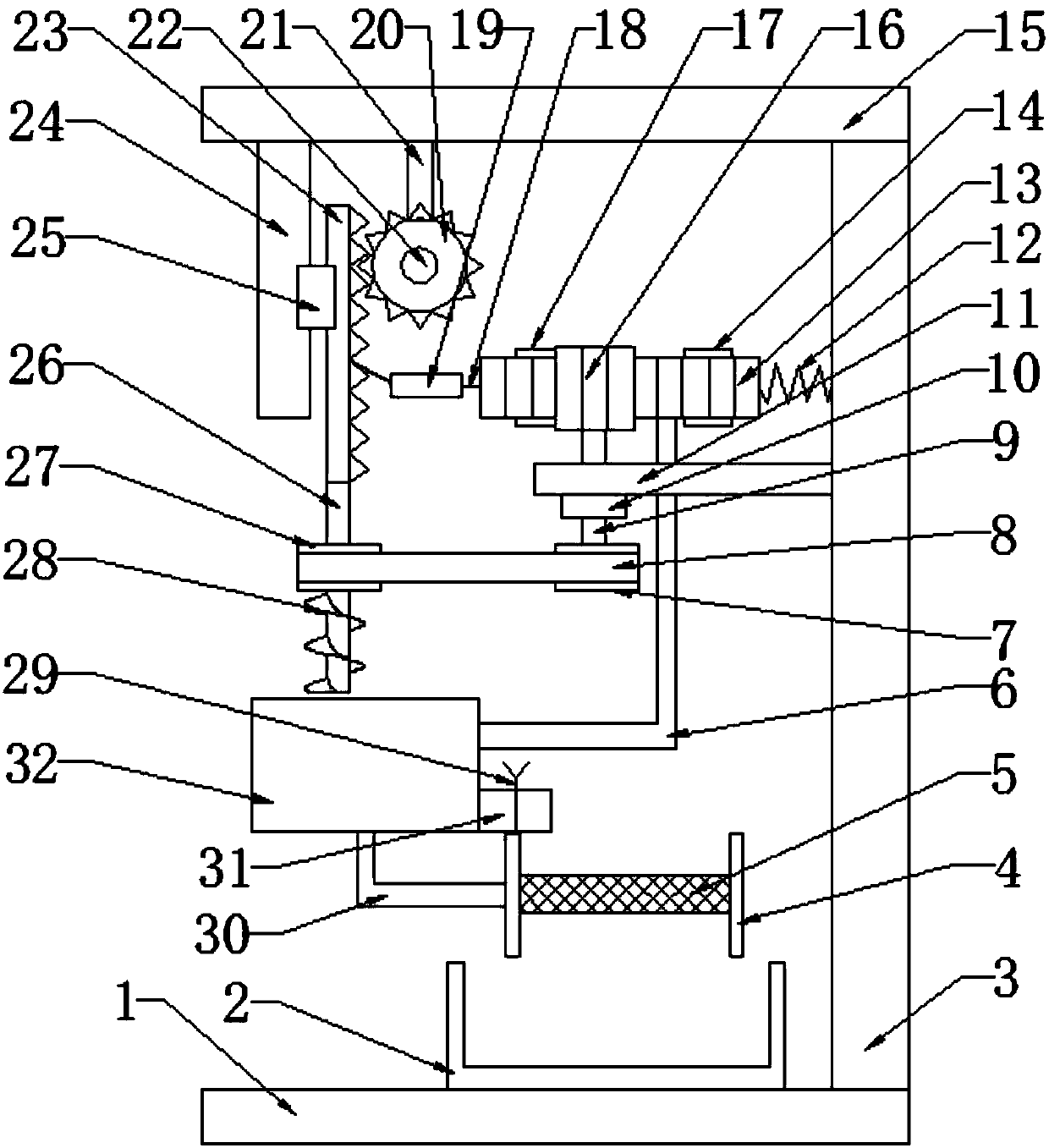
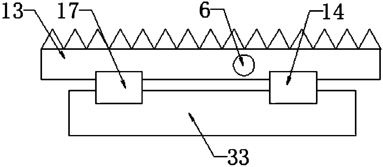
The invention provides a mixed stirring and sieving device of fodder, and belongs to the technical field of fodder processing. The mixed stirring and sieving device comprises a bottom plate, a vertical plate and a top plate, wherein the right side of the bottom plate is fixedly connected with the vertical plate; the top of the vertical plate is welded with the top plate; the left lower part of thetop plate is fixedly connected with a first sliding rail; the right side of the first sliding rail is connected with a first sliding block in a sliding way; the right side of the first sliding blockis sheathed with a first rack; the first rack is vertically arranged; the right side of the first rack is meshed with a first gear. The first rack is driven by the first gear to vertically move, the first rack pulls a soft rope to enable the second rack to horizontally move, a second gear meshed with the second rack rotates, the second gear rotates to drive a first belt pulley to rotate, and the first belt pulley drives a second belt pulley to rotate through a transmission belt; the second belt pulley controls a spindle to rotate, and the fodder in a mixing box is stirred and mixed by a spiralstirring vane below the spindle so as to be favorable for improving transmission and mixing efficiency.

Description

technical field [0001] The invention relates to the technical field of feed processing, in particular to a feed mixing and screening device. Background technique [0002] At present, in the breeding of poultry and livestock, the size of the feed powder particles is not uniform due to the insufficient preparation of the feed, and the feed is often screened and processed twice; to strictly ensure the uniformity of the size of the feed product, it is necessary to use a screening device for processing , in order to meet the qualified requirements; sometimes it is necessary to mix a variety of feeds together, and whether the feed is mixed uniformly will also affect the growth and development of animals; traditional feed screening methods can be roughly divided into manual screening and mechanical screening; manual screening, mainly It is to rely on manual use of sieves to select granular materials. This method is labor-intensive and the production efficiency is not high; mechanic...

Claims


Application Information

Patent Timeline
Patent Type & Authority Applications(China)
IPC IPC(8): B01F7/24B01F7/00A23N17/00B07B1/28
Inventor 高明飞
Owner 高明飞
Why Eureka
Eureka Blog
Learn More