Horizontal moving type cutting machine

A horizontal movement and cutting machine technology, applied in welding equipment, gas flame welding equipment, metal processing equipment, etc., can solve the problems of inconvenient horizontal adjustment and movement, and achieve the effect of convenient horizontal movement control, convenient movement and flexible movement adjustment

Inactive Publication Date: 2018-01-09
天津雅彩科技有限公司
View PDF0 Cites 0 Cited by
  • Summary
  • Abstract
  • Description
  • Claims
  • Application Information

AI Technical Summary

Problems solved by technology

Existing torches are inconvenient to move horizontally

Method used


Image

  • Horizontal moving type cutting machine

Examples


Embodiment Construction

[0012] In order to make the technical means, creative features, goals and effects achieved by the present invention easy to understand, the present invention will be further described below in conjunction with specific embodiments.

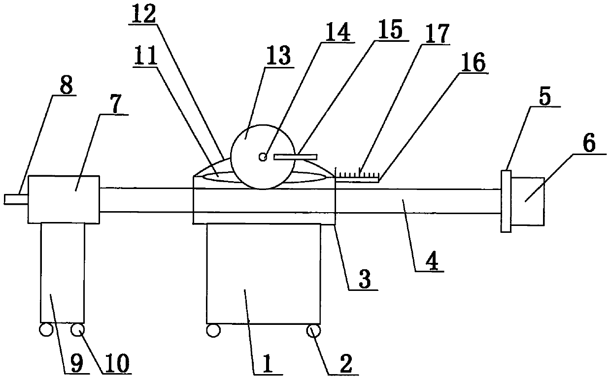
[0013] like figure 1 Shown, a kind of horizontal movable cutting machine comprises carrying case 1, and the bottom of carrying case 1 is provided with the first moving wheel 2 of several shapes and sizes identical, and the first moving wheel 2 is universal wheel; The end of the guide tube 3 is provided with a guide tube 3, the guide tube 3 is a tubular structure, and the guide tube 3 is arranged horizontally. One end of the moving pipe 4 is a free end, and the other end of the moving tube 4 is provided with a cutting machine 7, and the cutting machine 7 is provided with a cutting head 8; Two moving wheels 10, the second moving wheel 10 is a universal wheel; the upper side wall of the guide tube 3 is provided with a slot 11, and the upper side wal...


PUM


Abstract

The invention discloses a horizontally movable cutting machine, which comprises a carrying case. The end of the carrying case is provided with a guide tube, and a moving tube is set inside the guiding tube. One end of the moving tube is a free end, and the other end of the moving tube is provided with a The cutting machine is provided with a cutting head; the cutting machine is arranged on a moving seat. The invention facilitates the horizontal movement control of the cutting machine.

Description

technical field [0001] The invention relates to the field of metal cutting, in particular to a horizontally moving cutting machine. Background technique [0002] The torch generally has three switches, the top one is the high pressure oxygen switch, which is commonly known as the high wind switch; the bottom of the high wind switch is the mixed gas switch; the last switch is the acetylene switch. The order of use is: first turn on the acetylene switch, ignite, then adjust the size of the mixed gas and acetylene to control the size, preheat the object to be cut, and when it reaches the molten state, turn on the high wind switch to start cutting. Each torch can be equipped with several nozzles with different apertures to cut metals of different thicknesses. The nozzle numbers are 1#, 2#, and 3#, the larger the number, the thicker the cut metal. Existing torches are inconvenient for horizontal adjustment and movement. Contents of the invention [0003] Aiming at the defici...

Claims


Application Information

Patent Timeline
Patent Type & Authority Applications(China)
IPC IPC(8): B23K7/10
Inventor 蒋建杰
Owner 天津雅彩科技有限公司
Why Eureka
Try Eureka