
a valve

A valve and valve plate technology, applied in the field of valves, can solve the problems of complex operation, short service life, long opening and closing time, etc., and achieve the effect of simple operation, short opening and closing time, and prolonging service life

Active Publication Date: 2019-03-19
周常
View PDF7 Cites 1 Cited by
  • Summary
  • Abstract
  • Description
  • Claims
  • Application Information

AI Technical Summary

Problems solved by technology

[0004] The purpose of the present invention is to provide a valve which solves the problems of complex operation, long opening and closing time and short service life

Method used


Image

  • a valve
  • a valve
  • a valve

Examples


Embodiment Construction

[0033] The embodiments of the present invention will be described in detail below with reference to the accompanying drawings, but the present invention can be implemented in many different ways defined and covered by the claims.

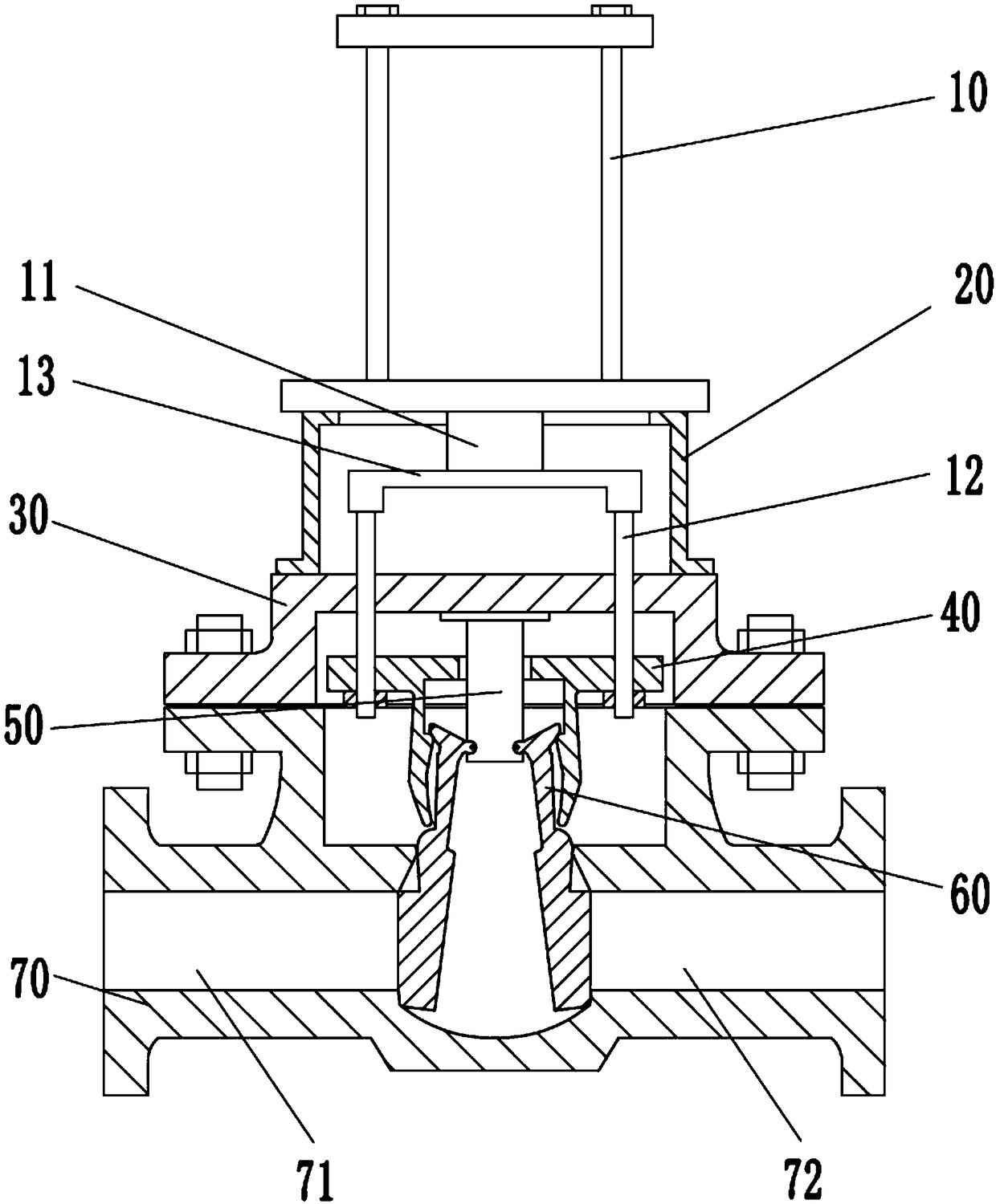
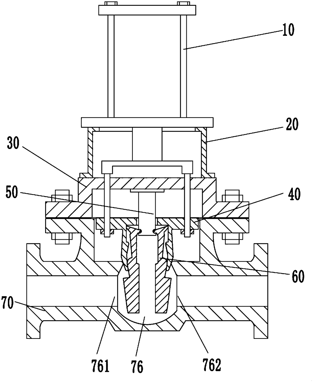
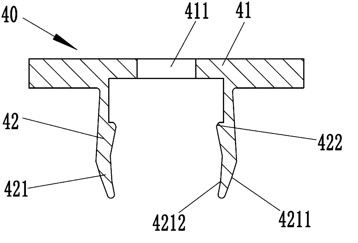
[0034] Refer below Figure 1 to Figure 5 To further explain this application, such as figure 1 with figure 2 A valve shown includes: a valve body 70 , a pair of valve plates 60 , a driving mechanism and a moving part 40 . Such as figure 1 with Figure 5 As shown, the valve body 70 has a front passage 71, a rear passage 72 and a valve chamber 76, and the valve chamber 76 communicates the front passage 71 and the rear passage 72, and the upper flange 75 of the valve body 70 It is connected with the upper cover 30 of the valve body 70 by screws, and the upper cover 30 is connected with the cylinder 10 of the drive mechanism through the support seat 20. The valve body 70 also has a left flange 73 and a right flange 73. flange 74, and the left flan...


PUM


Abstract

The invention provides a valve. The valve comprises a valve body, a pair of valve plates, a driving mechanism and a moving piece, wherein the valve body is provided with a front channel, a rear channel and a valve cavity; the front channel communicates with the rear channel by the valve cavity; the pair of valve plates is positioned in the valve body and is pivotally connected to a fixing plate ofthe valve body; the driving mechanism comprises a cylinder and a pair of guide columns; the cylinder is fixed on the valve body; the pair of guide columns is movably arranged on a top cover of the valve body; the upper parts of the pair of guide columns are separately connected with an extension shaft of the cylinder; and the moving piece is fixedly mounted on the lower parts of the pair of guidecolumns and is in contact with the pair of valve plates. The valve is novel in structure; and during working, an operator enables the cylinder to work so as to drive the moving piece to move vertically, and then the valve plates are driven to rotate around a hinged shaft to open and close a valve opening. Therefore, the valve has the advantages of simplicity in operation, short opening and closing time, capability of controlling the amount of water flowing through the valve and long service life.

Description

technical field [0001] The present invention relates to a valve. Background technique [0002] A valve is a device used to control the direction, pressure, and flow of a fluid in a fluid system. It is a device that enables or stops the flow of media (liquid, gas, powder) in piping and equipment and controls its flow. The valve is a control component in the pipeline fluid conveying system, which is used to change the passage section and the flow direction of the medium, and has the functions of diversion, cut-off, throttling, check, diversion or overflow and pressure relief. [0003] Due to the limitations of the selection of the driving structure of the existing valve, the operation of the valve is complicated and the opening and closing time is long, and because there is relative sliding between the sealing surface of the valve plate and the valve seat, long-term friction will cause damage, which affects the performance of the valve. Service life, especially gate valves. ...

Claims


Application Information

Patent Timeline
Patent Type & Authority Patents(China)
IPC IPC(8): F16K3/02F16K3/30F16K31/12
Inventor 邵丽娃
Owner 周常
Learn More