Drying device for fodder
A drying device and feed technology, which is applied in the direction of heating device, drying solid materials, drying, etc., can solve the problems of low drying efficiency and affecting the quality of feed, and achieve the effect of high drying efficiency, good production quality and uniform drying
- Summary
- Abstract
- Description
- Claims
- Application Information
AI Technical Summary
Problems solved by technology
Method used
Image

Examples
Embodiment 1
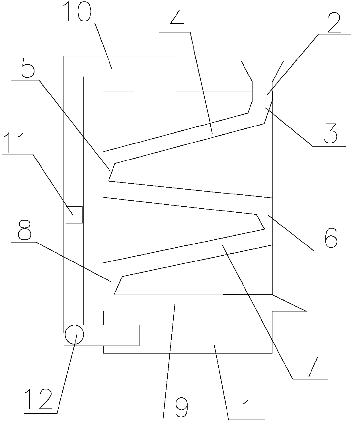
[0022] Such as figure 1 As shown, a drying device for feed of the present invention includes a drying box 1, which is connected with a drying pipeline in the drying box 1, and the drying pipeline includes a feed inlet 2 connected to the upper end of the drying box 1, and a feed inlet 2 Connected driving tube 3, inclined tube A4 connected with driving tube 3, bent tube A5 connected with inclined tube A4, inclined tube B connected with bent tube A5, bent tube B6 connected with inclined tube B, bent tube B6 The connected inclined pipe C7, the bent pipe C8 connected with the inclined pipe C7, the feed outlet 9 connected with the bent pipe C8, the driving pipe 3, the inclined pipe A4, and the inclined pipe C7 are inclined to the left, and the bent pipe A5, The turning pipe B6 and the turning pipe C8 are distributed sequentially from the top to the bottom of the drying box 1, and are all in contact with the inner wall of the drying box 1. The turning pipe A5 and the turning pipe C8 ...
Embodiment 2
[0024] The described drying device for feed comprises a drying box 1, and a drying pipeline is connected in the drying box 1, and the drying pipeline includes a feed inlet 2 connected to the upper end of the drying box 1, and a feed inlet 2 connected to the drying box 1. Driving tube 3, inclined tube A4 connected with driving tube 3, bent tube A5 connected with inclined tube A4, inclined tube B connected with bent tube A5, bent tube B6 connected with inclined tube B, bent tube B6 connected with Inclined pipe C7, the bend pipe C8 connected with the inclined pipe C7, the feed outlet 9 connected with the bend pipe C8, the drive pipe 3, the inclined pipe A4, and the inclined pipe C7 are inclined to the lower left, and the bend pipe A5, the bend pipe B6 and crutches C8 are distributed sequentially from the top of the drying box 1 to the bottom, and all contact with the inner wall of the drying box 1. The crutches A5 and C8 are on one side of the drying box 1, and the crutches B6 are...
Embodiment 3
[0026] The described drying device for feed comprises a drying box 1, and a drying pipeline is connected in the drying box 1, and the drying pipeline includes a feed inlet 2 connected to the upper end of the drying box 1, and a feed inlet 2 connected to the drying box 1. Driving tube 3, inclined tube A4 connected with driving tube 3, bent tube A5 connected with inclined tube A4, inclined tube B connected with bent tube A5, bent tube B6 connected with inclined tube B, bent tube B6 connected with Inclined pipe C7, the bend pipe C8 connected with the inclined pipe C7, the feed outlet 9 connected with the bend pipe C8, the drive pipe 3, the inclined pipe A4, and the inclined pipe C7 are inclined to the lower left, and the bend pipe A5, the bend pipe B6 and crutches C8 are distributed sequentially from the top of the drying box 1 to the bottom, and all contact with the inner wall of the drying box 1. The crutches A5 and C8 are on one side of the drying box 1, and the crutches B6 are...
PUM
| Property | Measurement | Unit |
|---|---|---|
| Angle | aaaaa | aaaaa |
Abstract
Description
Claims
Application Information
 - R&D
- Intellectual Property
- Life Sciences
- Materials
- Tech Scout
- Unparalleled Data Quality
- Higher Quality Content
- 60% Fewer Hallucinations
Browse by: Latest US Patents, China's latest patents, Technical Efficacy Thesaurus, Application Domain, Technology Topic, Popular Technical Reports.
© 2025 PatSnap. All rights reserved.Legal|Privacy policy|Modern Slavery Act Transparency Statement|Sitemap|About US| Contact US: help@patsnap.com