Eureka AIR delivers breakthrough ideas for toughest innovation challenges, trusted by R&D personnel around the world.

Microwave-based vehicle queuing length detection method and system

A technology of queuing length and detection method, which is applied in the traffic control system of road vehicles, traffic flow detection, traffic control system, etc., can solve the problem of inability to provide accurate basis for intelligent traffic system command, reduce the accuracy of vehicle queuing length at intersections, and reduce pollution. And other issues

Pending Publication Date: 2018-01-09
NANJING HURYS INTELLIGENT TECH CO LTD
View PDF0 Cites 12 Cited by
  • Summary
  • Abstract
  • Description
  • Claims
  • Application Information

AI Technical Summary

Problems solved by technology

In the real environment, the lane lines are parallel, but due to the imaging of the camera lens, the imaged lane lines are no longer parallel
In addition, there are many vehicles at traffic intersections, and the lane lines are severely worn and polluted. It is not easy to identify the lanes and divide the detection area.
Moreover, if the image is collected by light, shadows, bad weather, and passing pedestrians, it will cause a large-area occlusion problem in the vehicle image, making it difficult to accurately segment the vehicle in the image, and ultimately reduce the number of vehicles at the intersection. The accuracy of queue length detection cannot provide an accurate basis for intelligent transportation system command

Method used


Image

  • Microwave-based vehicle queuing length detection method and system
  • Microwave-based vehicle queuing length detection method and system
  • Microwave-based vehicle queuing length detection method and system

Examples


Embodiment Construction

[0049] The specific embodiments of the present invention will be further described below in conjunction with the accompanying drawings. It should be noted here that the descriptions of these embodiments are used to help understand the present invention, but are not intended to limit the present invention. In addition, the technical features involved in the various embodiments of the present invention described below may be combined with each other as long as they do not constitute a conflict with each other.

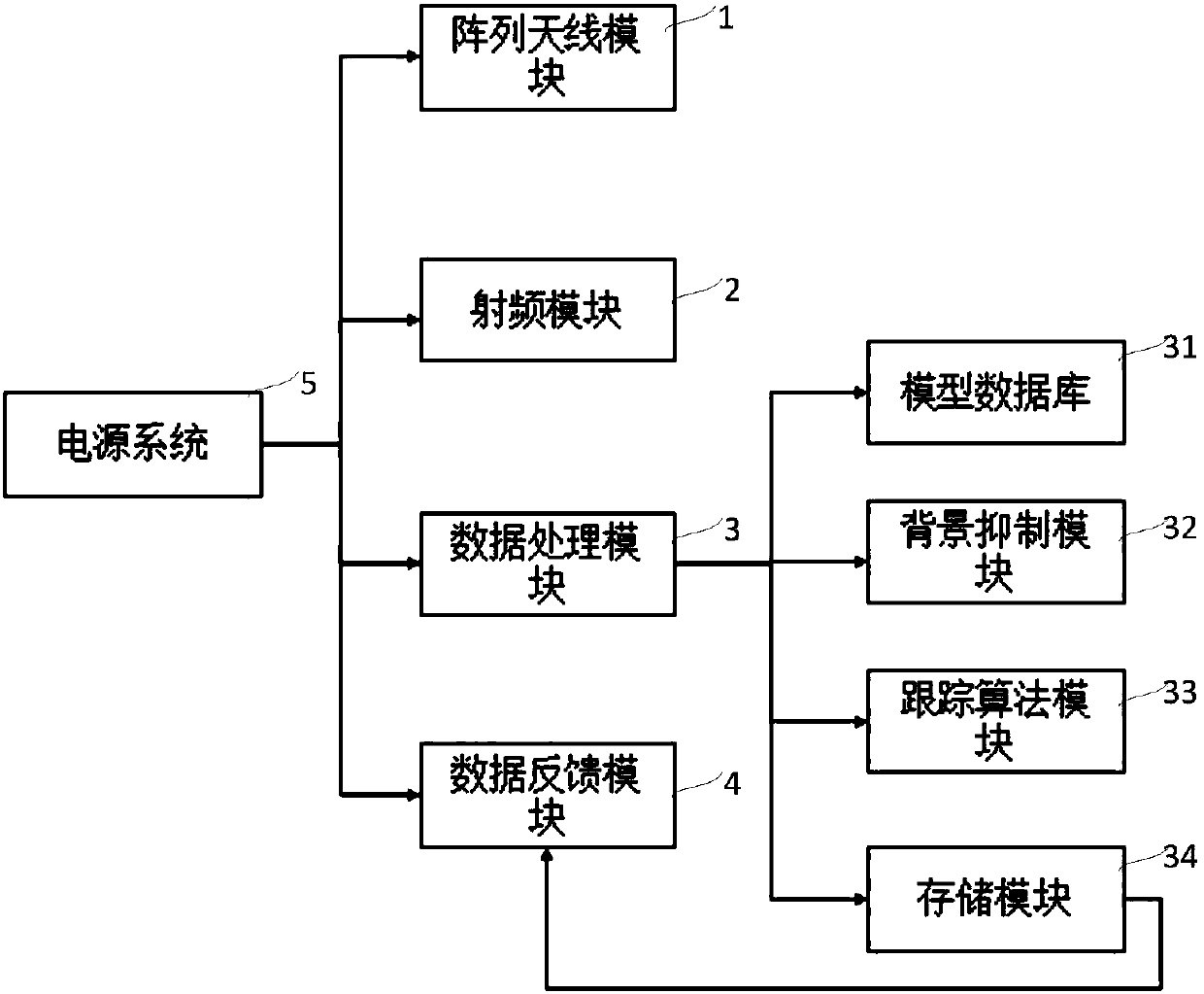
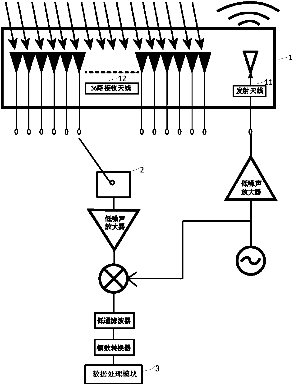
[0050] Such as figure 2 As shown, the present invention includes an array antenna module 1 , a radio frequency module 2 , a data processing module 3 , and a data feedback module 4 . The array antenna module 1 and the radio frequency module 2 can be used to transmit multiple beams in the detection coverage area, and receive the multiple beams returned. The schematic diagram of transmission and reception can be found in image 3 . The radio frequency module 2 is compo...


PUM


Abstract

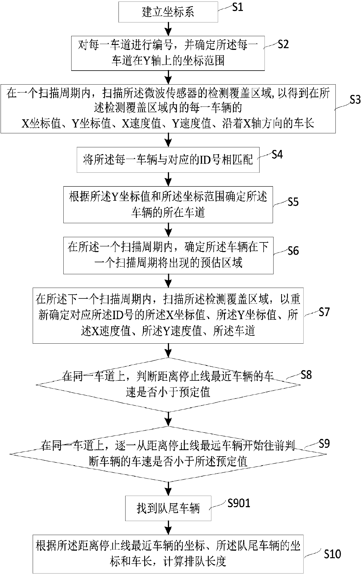
The invention discloses a microwave-based vehicle queuing length detection method and system. The system includes an array antenna module, a radio frequency module, a model database, a tracking algorithm module and a data processing module; the array antenna module and the radio frequency module are used for transmitting a plurality of beams in a detection coverage area and receiving returned beams; the model database is used for building a coordinate system at the detection coverage area and numbering each lane so as to determine the coordinate range of each lane on a Y axis; the tracking algorithm module is used for analyzing a plurality of beams returned within one scanning period, is also used for determining a predicted region where a vehicle will appear in a next scanning period, andis further used for analyzing a plurality of beams returned within the next scanning period; and the data processing module is used for integrating the data of the model database and tracking algorithm module and determining whether the speed of the vehicle is smaller than a predetermined value so as to calculate queuing length. With the method and system of the invention adopted, the state of the vehicle can be tracked in real time, the queuing situation of the vehicle can be analyzed in real time, the influence of an environment can be avoided, and a basis can be provided for the control oftraffic signals.

Description

technical field [0001] The invention relates to the field of traffic control, in particular to a microwave-based vehicle queue length detection method and system. Background technique [0002] Transportation is the lifeblood of a city and the most important infrastructure in the city's economy and people's lives. Traffic control is a social public welfare undertaking related to the national economy and the people's livelihood. It is closely related to the production and life of the public. The stable and sustainable development of cities and the improvement of people's living standards play an important role. Over the past 30 years of reform and opening up, with the rapid economic and social development of our country and the gradual expansion of urban population, the number of motor vehicles has shown a trend of rapid growth. The existing road network has been unable to meet the growing traffic demand, resulting in urban traffic accidents A series of problems such as freq...

Claims


Application Information

Patent Timeline
IPC IPC(8): G08G1/01G08G1/065
Inventor 张德锋章庆顾丹丹
Owner NANJING HURYS INTELLIGENT TECH CO LTD
Why Eureka
Eureka Blog
Learn More