Gate drive circuit and display device

A gate drive circuit and gate drive technology, applied to static indicators, instruments, etc., can solve problems such as difficulty, unsatisfactory effect, serious threshold voltage drift, etc., and achieve stable threshold voltage and reduced power consumption.

Active Publication Date: 2018-01-09
KUSN INFOVISION OPTOELECTRONICS
View PDF8 Cites 5 Cited by
  • Summary
  • Abstract
  • Description
  • Claims
  • Application Information

AI Technical Summary

Problems solved by technology

However, these methods are not only very difficult to implement, but also the effect is not very ideal. For example, the threshold voltage drift cannot be completely solved by the process; although the AC signal can reduce the threshold voltage drift, the threshold voltage drift is still very serious; it can only be reduced. Threshold voltage drifts, but cannot suppress

Method used


Image

  • Gate drive circuit and display device
  • Gate drive circuit and display device
  • Gate drive circuit and display device

Examples


Embodiment Construction

[0024] In order to make the purpose and solution of the present invention clearer and facilitate implementation, the present invention will be further described in detail below in conjunction with the accompanying drawings. In the various figures, identical elements are indicated with similar reference numerals. For the sake of clarity, various parts in the drawings have not been drawn to scale. Also, some well-known parts may not be shown.

[0025] In the following, numerous specific details of the present invention are described in order to provide a clearer understanding of the present invention. However, the invention may be practiced without these specific details, as will be understood by those skilled in the art.

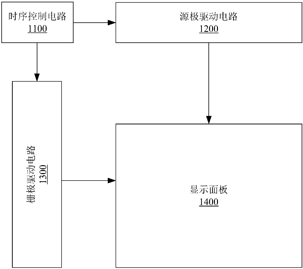
[0026] figure 1 A schematic structural diagram of a display device according to an embodiment of the present invention is shown, the display device includes a timing control circuit 1100, a source drive circuit 1200, a gate drive circuit 1300, and a displa...


PUM


Abstract

The invention discloses a gate drive circuit. The gate drive circuit comprises multiple gate drive units which are controlled by a first mode signal and a second mode signal. Each gate drive unit comprises an input module which is used for controlling the voltage of a first node according to a former gate transmission signal and a latter gate transmission signal; a control module which is used forgenerating a first control signal when the first mode signal is effective and generating a second control signal when the second mode signal is effective, wherein the first mode signal and the secondmode signal are alternately effective; a pull-down module which is used for pulling down the voltage of the first node when the first control signal or the second control signal is effective; a resetmodule which is used for resetting the second control signal to the low level when the first control signal is effective and resetting the first control signal to the low level when the second control signal is effective; and an output module which is used for generating the present gate drive signal according to the first control signal, the second control signal and the voltage of the first node.

Description

technical field [0001] The present invention relates to the field of display technology, and more particularly, to a gate drive circuit and a display device. Background technique [0002] A display device generally includes a display panel, a gate driving circuit and a source driving circuit. Wherein, the display panel includes a pixel array formed by a plurality of pixel units, and each pixel unit includes a thin film transistor. In the pixel array, the gates of the thin film transistors in the pixel units in the same row are connected to the gate drive circuit through the same scan line, and the gate drive circuit selects each row of pixel units in the pixel array row by row through multiple scan lines ; The sources or drains of the thin film transistors in the pixel units in the same column are connected to the source drive circuit through the same data line, and the source drive circuit applies grayscale voltages to the pixel units in each column through multiple data l...

Claims


Application Information

Patent Timeline
Patent Type & Authority Applications(China)
IPC IPC(8): G09G3/20
Inventor 李海波郑会龙邹忠飞陈尧
Owner KUSN INFOVISION OPTOELECTRONICS
Why Eureka
Try Eureka