Waste silk powder stirring device

A stirring device and powder technology, which is applied to mixers with rotary stirring devices, accessories of mixers, rayon recycling, etc., can solve the problems of low work efficiency, easy to fly around, slow falling speed of waste silk powder, etc., to improve the use of The effect of speeding up the falling speed and improving work efficiency

Inactive Publication Date: 2018-01-12
JIANGSU GUANGSHENGYUAN TECH DEV
View PDF0 Cites 1 Cited by
  • Summary
  • Abstract
  • Description
  • Claims
  • Application Information

AI Technical Summary

Problems solved by technology

[0002] As we all know, in the textile industry, a large amount of fiber waste silk will be produced after the fiber raw material in the raw material cylinder is processed. After the fiber waste silk is cut and crushed, it will be supplied to the raw material cylinder through the conveying device as a raw material for recycling. The waste silk powder mixing device is An auxiliary device for stirring waste silk powder for subsequent output, which is widely used in the field of waste silk recovery; the existing waste silk powder stirring device includes a working box, a placing frame, a motor and a discharge pipe, The working box is installed obliquely on the top of the shelf. There is a working chamber inside the working box. The top of the working box is provided with a feeding port. The feeding port communicates with the working chamber, and a cover is set on the feeding port. , the top output end of the motor is provided with a rotating shaft, and a stirring blade

Method used


Image

  • Waste silk powder stirring device
  • Waste silk powder stirring device
  • Waste silk powder stirring device

Examples


Example Embodiment

[0015] The specific embodiments of the present invention will be described in further detail below in conjunction with the drawings and embodiments. The following examples are used to illustrate the present invention, but not to limit the scope of the present invention.

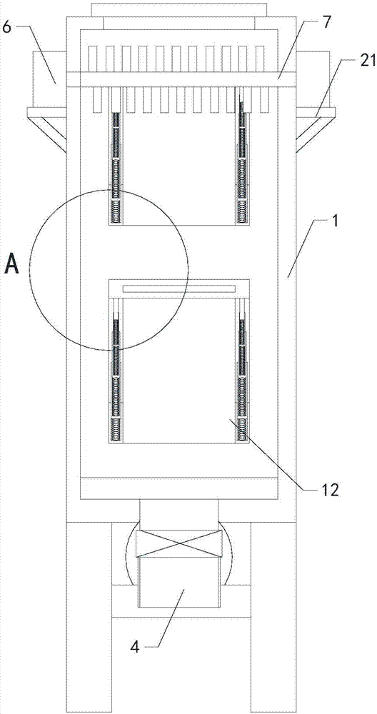
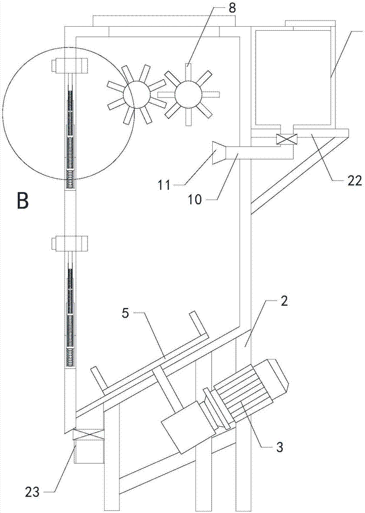
[0016] Such as Figure 1 to Figure 4 As shown, a waste silk powder stirring device of the present invention includes a working box 1, a placing frame 2, a motor 3, and a discharge pipe 4. The working box is inclinedly arranged on the top of the placing frame, and a working cavity is provided in the working box. The top is provided with a feed port, the feed port communicates with the working chamber, and a blocking cover is provided on the feed port. The motor is provided at the bottom of the working box, and the top output end of the motor is provided with a rotating shaft, and the rotating shaft is provided with The mixing blade 5, the mixing blade is located in the working chamber, the discharge pipe is arra...


PUM


Abstract

The invention relates to the technical field of waste silk recovery, in particular to a waste silk powder stirring device. Waste silk powder can be prevented from being scattered at a feed inlet. In addition, the falling speed of the waste silk powder in a working cavity is increased, and the working efficiency is improved. Moreover, the internal condition of the working cavity can be viewed, so that the usability is improved. The device comprises a work box, a placement rack, a motor and a discharge pipe, wherein the work box is obliquely arranged at the top end of the placement rack, and a control valve is arranged on the discharge pipe. The device further comprises a first crushing motor and a second crushing motor, wherein a first transmission roller is arranged at the right output endof the first crushing motor, and multiple groups of crushing cutting blades are arranged on the first transmission roller and a second transmission roller. The device further comprises a containing box, a communicating pipe and a sprinkler, wherein the outlet end of the communicating pipe penetrate through the rear end of the work box, and is connected with the inlet end of the sprinkler. The device further comprises two groups of transparent baffle plates and two groups of cleaning devices, and the two groups of cleaning devices are arranged on the two groups of transparent baffle plates respectively.

Description

technical field [0001] The invention relates to the technical field of waste silk recycling, in particular to a waste silk powder stirring device. Background technique [0002] As we all know, in the textile industry, a large amount of fiber waste silk will be produced after the fiber raw material in the raw material cylinder is processed. After the fiber waste silk is cut and crushed, it will be supplied to the raw material cylinder through the conveying device as a raw material for recycling. The waste silk powder mixing device is An auxiliary device for stirring waste silk powder for subsequent output, which is widely used in the field of waste silk recovery; the existing waste silk powder stirring device includes a working box, a placing frame, a motor and a discharge pipe, The working box is installed obliquely on the top of the shelf. There is a working chamber inside the working box. The top of the working box is provided with a feeding port. The feeding port communic...

Claims


Application Information

Patent Timeline
IPC IPC(8): B01F7/04B01F15/02D01F13/00B02C18/14
CPCY02P70/62
Inventor 金传广李欣欣宋大顺尤汉春刘兆诚徐晓洪陈西府
Owner JIANGSU GUANGSHENGYUAN TECH DEV
Why Eureka
Try Eureka