Silicone rubber insulator injection mold demolding device

A silicone rubber insulation and injection mold technology, which is used in household appliances, other household appliances, household components, etc., can solve the problems of reducing the production efficiency of rubber insulators, scrapping insulator devices, leaving pits, etc., to reduce the difficulty of demolding, Easy demoulding and scratch prevention effect

Active Publication Date: 2018-01-12
硅美德橡塑科技(昆山)有限公司
View PDF6 Cites 7 Cited by
  • Summary
  • Abstract
  • Description
  • Claims
  • Application Information

AI Technical Summary

Problems solved by technology

[0003] (1) Most of the existing silicone rubber insulator injection mold release devices use metal ejector rods to eject the rubber insulator from the bottom of the injection mold after the insulator is cooled and formed, so as to achieve the purpose of separating the rubber insulator from the inner surface of the mold. Although this method is simple, for the newly formed rubber parts, using a large extrusion force will inevitably leave pits on the surface. If you want to avoid pits as much as possible, you need to wait for a long time to make the rubber The insulator is completely cooled and recovers the mechanical properties of its material itself, so that the production efficiency of rubber insulators is reduced due to the limitation of the demoulding device;
[0004] (2) Because the existing silicone rubber insulator injection mold release device uses unidirectional stress to release the formed insulator, it often causes the silicone rubber insulator to scratch against the inner wall of the mold during demoulding, which is easy to form on the surface of the silicone rubber insulator. The burr, chamfer or edge along the stress direction needs to be specially polished after demolding. In addition, for the soft silicone rubber, sometimes the side may be torn when the cooling is not complete. Cause scrapping of insulator devices;

Method used


Image

  • Silicone rubber insulator injection mold demolding device
  • Silicone rubber insulator injection mold demolding device

Examples


Embodiment

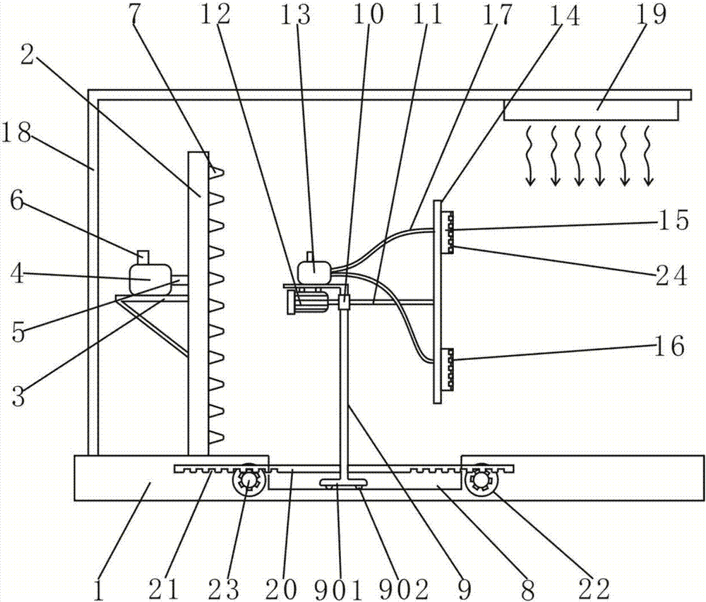
[0024] Such as figure 1 As shown, the present invention provides a silicone rubber insulator injection mold release device, including a base 1, the upper surface of the base 1 is fixedly connected with a high-pressure chamber 2, and the left side of the high-pressure chamber 2 is fixedly connected with an air chamber through a tripod 3. Compressor 4, the air compressor 4 is connected to the inside of the high-pressure chamber 2 through the air pipe 5, the top of the air compressor 4 is provided with an inlet pipe 6, and the right side surface of the high-pressure chamber 2 is fixedly connected with a horizontal injection nozzle 7, The injection nozzles 7 are distributed on the right side of the high-pressure chamber 2 at equal intervals in turn, and each injection nozzle 7 is located on the same vertical line. The injection nozzles 7 are conical, and the diameter of the end is 2mm.

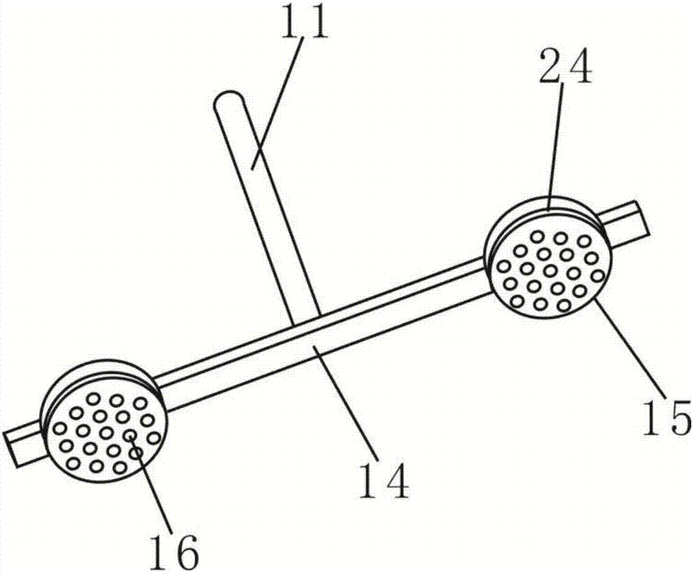
[0025] Such as figure 1 and figure 2 As shown, the center of the base 1 is provided with a ...


PUM

PropertyMeasurementUnit
diameteraaaaaaaaaa

Abstract

The invention discloses a silicone rubber insulator injection mold demolding device which comprises a base. The base is connected with a high-pressure cavity. The left side of the high-pressure cavityis connected with an air compressor. The surface of the right side of the high-pressure cavity is connected with horizontal jet nozzles. The base is provided with a rectangular groove. A stand columnis arranged in the rectangular groove. A bearing is arranged at the top end of the stand column. A rotary shaft is arranged in the bearing. The left side of the rotary shaft is connected with a motorand fixedly connected with a rotary frame. The two ends of the rotary frame are fixedly provided with negative-pressure cavities. Adsorption holes are formed in the right sides of the negative-pressure cavities. The left side of the base is connected with an L-shaped support. The tail end of the L-shaped support is provided with an air cooler. By arranging the high-pressure cavity and the jet nozzles, even and gentle air force is used for demolding, no pit is left in the surface of an insulator, by arranging the rotary frame and the negative-pressure cavities, rotation and forward pushing areconducted at the same time, and the demolding difficulty is lowered.

Description

technical field [0001] The invention relates to a mold demoulding device, in particular to a silicone rubber insulator injection mold demoulding device. Background technique [0002] Insulator is a special insulation control, which can play an important role in overhead transmission lines. Insulators were mostly used on utility poles in the early years, and gradually developed in the high-voltage wire connection tower. Many disc-shaped insulators, silicone rubber Insulators are the most commonly used types of insulators. The silicone rubber insulator injection mold release device currently in use has the following disadvantages: [0003] (1) Most of the existing silicone rubber insulator injection mold release devices use metal ejector rods to eject the rubber insulator from the bottom of the injection mold after the insulator is cooled and formed, so as to achieve the purpose of separating the rubber insulator from the inner surface of the mold. Although this method is sim...

Claims


Application Information

Patent Timeline
Patent Type & Authority Applications(China)
IPC IPC(8): B29C45/43B29C45/72B29L31/34
Inventor 陈波
Owner 硅美德橡塑科技(昆山)有限公司
Why Eureka
Try Eureka