

Useless object treatment method applied to construction site
A processing method and site technology, applied in the field of construction, can solve the problems of affecting life safety, four-column garbage compressors without any protective device, falling over, etc., to protect life safety, facilitate safety management, and reduce accident rates.
- Summary
- Abstract
- Description
- Claims
- Application Information
AI Technical Summary
Problems solved by technology
Method used
Image

Examples
Embodiment 1
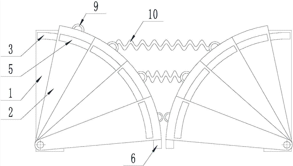
[0046] Such as Figure 1-Figure 10 As shown, the present invention is applied to the waste treatment method of the construction site, comprising the following steps:
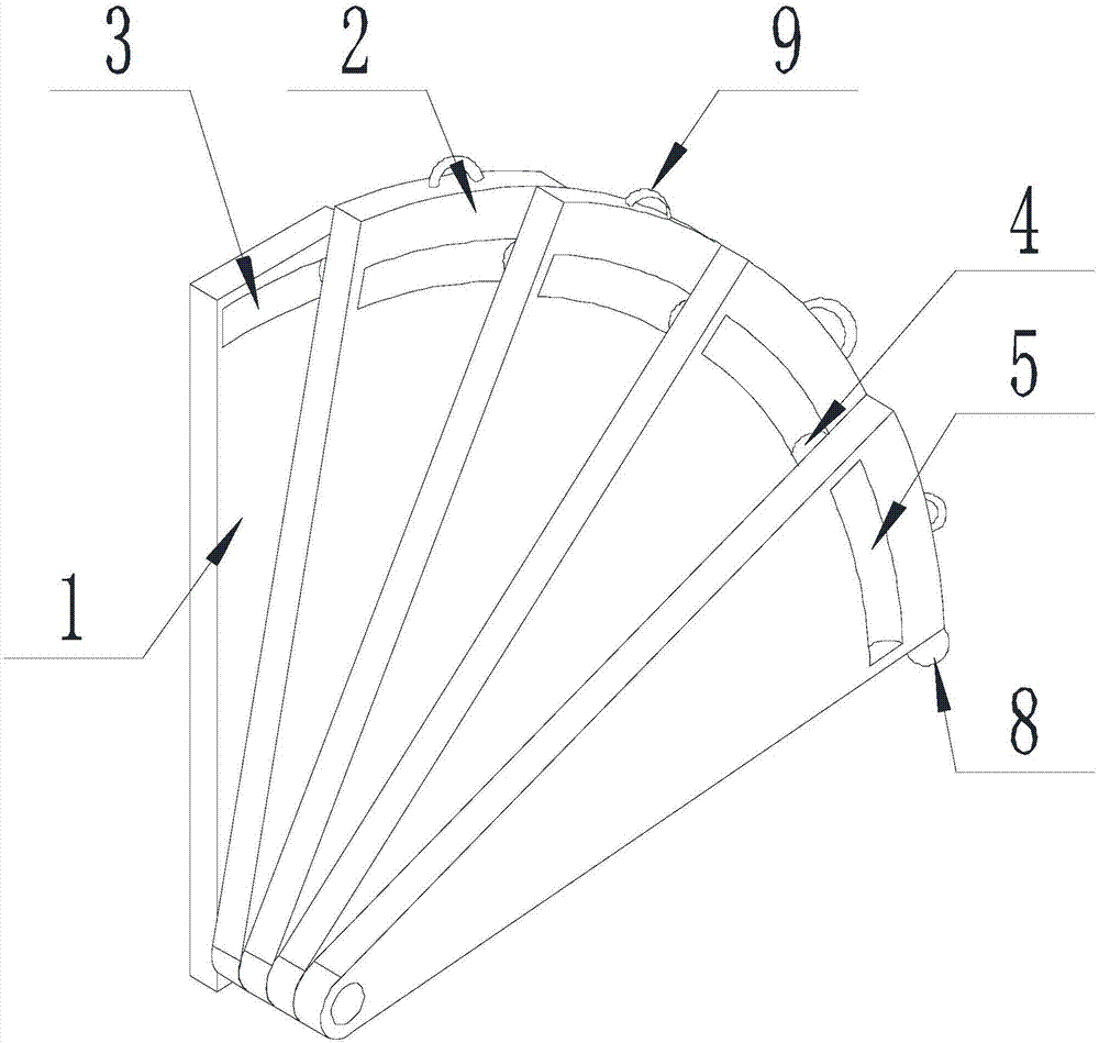
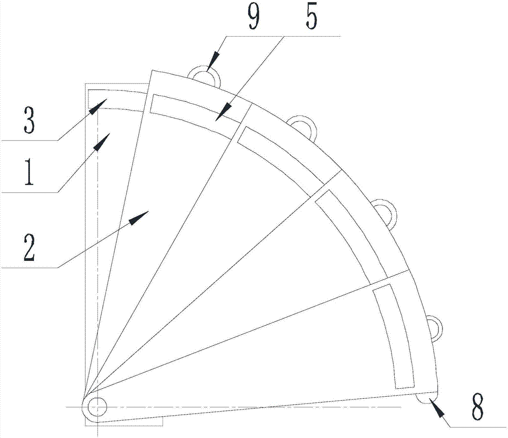
[0047] Step A installation: Install the fixed plate 1 and the rotating assembly sequentially connected on one side of the four-post vertical garbage compression station 11, the rotating assembly includes several overlapping moving plates 2, one end of the fixed plate 1 and the moving plate One ends of 2 are hinged to each other, and both fixed plate 1 and moving plate 2 are perpendicular to the hinge axis;
[0048] Step B Rotate: pull the movable plate 2 to rotate the movable plate 2 and cover one side of the four-post vertical garbage compression station 11 .
[0049] A guide groove 3 is provided on the surface of the fixed plate 1 close to the moving plate 2, and guide blocks 4 are arranged on the surface of the moving plate 2 close to the fixed plate 1, and the moving plate 2 is far away from the fixed plate 1...
Embodiment 2
[0053] The present invention is based on embodiment 1, and the present invention is further described.
[0054] Such as Figure 1-Figure 10 As shown, the present invention is used for the protection equipment of the useless object processing station on the construction site, the opening dimensions of the guide groove 3 and the chute 5 are all smaller than the bottom size of the groove, and the cross-sectional dimensions of the guide groove 3 and the chute 5 are the same as those of the guide block 4 The cross-sectional dimensions are the same.
[0055] The cross-sections of the guide groove 3 and the chute 5 are all arc-shaped, the guide block 4 is spherical, and the diameters in the cross-section of the guide groove 3 and the chute 5 are consistent with the spherical diameter of the guide block 4 .
[0056] The cross-sections of the guide block 4 and the slot matched with it are both arranged in an arc shape, which is beneficial to the stability of the rotating movable plate...
PUM
 Abstract
Description
Claims
Application Information