
Rolling disc type working device and slide revolving support thereof

A technology of slewing support and slewing frame, which is applied to the chassis of agricultural machinery, mechanically driven excavators/dredgers, agricultural machinery and machinery, etc., can solve the problem of low frequency adjustment of blade rotation angle, rolling ball and raceway pitting , lubricating oil film is not easy to form and other problems, to avoid abnormal wear, reduce replacement cost, reduce contact stress

Pending Publication Date: 2018-01-12
SHANDONG LINGONG CONSTR MACHINERY
View PDF6 Cites 4 Cited by
  • Summary
  • Abstract
  • Description
  • Claims
  • Application Information

AI Technical Summary

Problems solved by technology

[0004] 1. In most working conditions and working hours, the left and right rotation angle of the blade is generally within 15~50゜, the range of the blade rotation angle is small, and the adjustment frequency and speed of the blade rotation angle are low during the construction process and other characteristics, so most of the working load and instantaneous impact occur on the rolling ball and raceway within 15-50° of the rolling slewing support, so that the rolling ball and raceway are partially loaded
At the same time, the rolling ball and the raceway are mostly in line contact or point contact, the contact stress is relatively high, and the lubricating oil film is not easy to form, resulting in early fatigue damage such as pitting corrosion on the rolling ball and raceway in the range of 15-50°;
[0005] 2. When the rolling ball or raceway of the rolling slewing support is damaged by pitting and other damages that affect normal use, the entire rolling slewing support must be replaced, and the replacement cost is high

Method used


Image

  • Rolling disc type working device and slide revolving support thereof
  • Rolling disc type working device and slide revolving support thereof
  • Rolling disc type working device and slide revolving support thereof

Examples


Embodiment 1

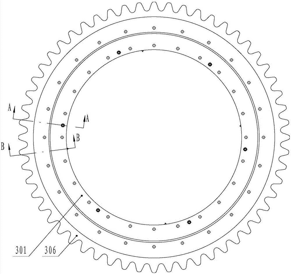
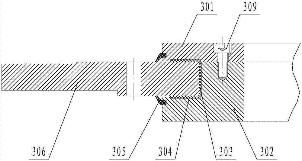
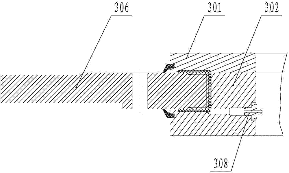
[0030] Embodiment one: if figure 1 and figure 2 As shown, the sliding slewing support 3 includes an upper fixed plate 301 and a lower fixed plate 302, a sliding ring gear is arranged between the upper fixing plate 301 and the lower fixing plate 302, the sliding ring gear is a sliding outer gear ring 306, and the sliding outer gear ring 306 Located on the outer side of the upper fixing plate 301 and the lower fixing plate 302, a composite sliding bearing II 304 and a sealing ring 305 are provided respectively above and below the sliding outer ring gear 306 and between the upper fixing plate 301 and the lower fixing plate 302, and the sealing ring 305 is VR-type sealing ring, a composite sliding bearing I303 is provided between the inner side of the sliding outer gear ring 306 and the lower fixing plate 302; image 3 As shown, the sliding surface of the sliding outer ring gear 306 in contact with the upper fixing plate 301 and the lower fixing plate 302 is respectively provide...

Embodiment 2

[0033] Embodiment two: if Figure 5 As shown, the sliding ring gear is a sliding ring gear 307, and the sliding ring gear 307 is located inside the upper fixing plate 301 and the lower fixing plate 302; the others are the same as the first embodiment.

Embodiment 3

[0034] Embodiment three: as Figure 6 As shown, the rolling disc type working device includes a traction frame 2 of a grader and a revolving frame 4, and the sliding slewing support 3 described in the first embodiment is arranged between the traction frame 2 and the revolving frame 4 of the grader.


PUM


Abstract

The invention discloses a rolling disc type working device and a slide revolving support thereof, and belongs to the field of engineering machinery. The device mainly comprises an upper fixed plate and a lower fixed plate; a slide gear ring is arranged between the upper fixed plate and the lower fixed plate; composite slide bearings II and sealing rings are arranged above and below the slide gearring and between the upper fixed plate and the lower fixed plate; a composite slide bearing I is arranged between the inner side of a slide outer gear ring and the lower fixed plate; lubricating oil tanks are respectively formed in the side surfaces, contacted with the upper fixed plate and the lower fixed plate, of the slide gear ring; lubricating holes are formed in the lower fixed plate, and communicate with the lubricating oil tanks; and lubricating oil cups are arranged in the lubricating holes. A sliding end and a fixed end are in surface contact; a lubricating oil film is easier to form; the lubrication is more sufficient; the replacement cost is low; and failed parts are only replaced. The device is mainly applied to a land leveler.

Description

technical field [0001] The invention belongs to the field of construction machinery, and in particular relates to a rolling-disk type working device and a sliding and rotating support thereof. Background technique [0002] The grader realizes various tasks such as leveling roads and farmland, scraping side slopes, and scraping inclined ditches through the blade working device. During work, it is necessary to drive the slewing frame and the blade to rotate through the slewing drive mechanism, so as to realize the adjustment of the rotation angle of the blade to meet the needs of various working conditions. At present, there are two connection methods for the rotary frame of the motor grader, the blade and the traction frame: one is the tray-type working device, and the rotary frame is connected to the traction frame through the guide plate, the pressure plate, and the cost of this connection is high, and it is easy to cause abnormal wear and tear. After the occurrence, the e...

Claims


Application Information

Patent Timeline
Patent Type & Authority Applications(China)
IPC IPC(8): E02F3/76E02F3/80A01B29/00A01B51/00
Inventor 迟峰王永苗国华崔元福赵旭光冯克祥王桂印刘洪超李勇
Owner SHANDONG LINGONG CONSTR MACHINERY
Learn More