
Piezoelectric pump and electronic product

A technology of piezoelectric pumps and piezoelectric vibrators, which is applied in the field of piezoelectric devices, can solve problems such as hindering airflow movement, reducing power consumption, and large capacitance, and achieves the effect of large diaphragm vibration, low power consumption, and large volume change

Active Publication Date: 2018-01-12
SUZHOU PANT PIEZOELECTRIC TECH
View PDF5 Cites 9 Cited by
  • Summary
  • Abstract
  • Description
  • Claims
  • Application Information

AI Technical Summary

Problems solved by technology

However, there are some problems in these methods: the driving vibrator has a solid circular shape or a square piezoelectric ceramic sheet with a large electrode surface, so its capacitance is relatively large, which is not conducive to reducing power consumption; The one-way valve for opening and closing, because the one-way valve for passive opening and closing needs the vacuum degree or pressure in the pump chamber to reach a certain threshold to open and close, the opening and closing of the valve body has hysteresis, which hinders the movement of airflow; The flow resistance difference is generally a valveless pump, and the output pressure is small

Method used


Image

  • Piezoelectric pump and electronic product
  • Piezoelectric pump and electronic product
  • Piezoelectric pump and electronic product

Examples


Embodiment Construction

[0037] The technical solutions of the present invention will be clearly and completely described below in conjunction with the accompanying drawings. Apparently, the described embodiments are some of the embodiments of the present invention, but not all of them. Based on the embodiments of the present invention, all other embodiments obtained by persons of ordinary skill in the art without making creative efforts belong to the protection scope of the present invention.

[0038] In the description of the present invention, it should be noted that the terms "center", "upper", "lower", "left", "right", "vertical", "horizontal", "inner", "outer" etc. The indicated orientation or positional relationship is based on the orientation or positional relationship shown in the drawings, and is only for the convenience of describing the present invention and simplifying the description, rather than indicating or implying that the referred device or element must have a specific orientation, ...


PUM


Abstract

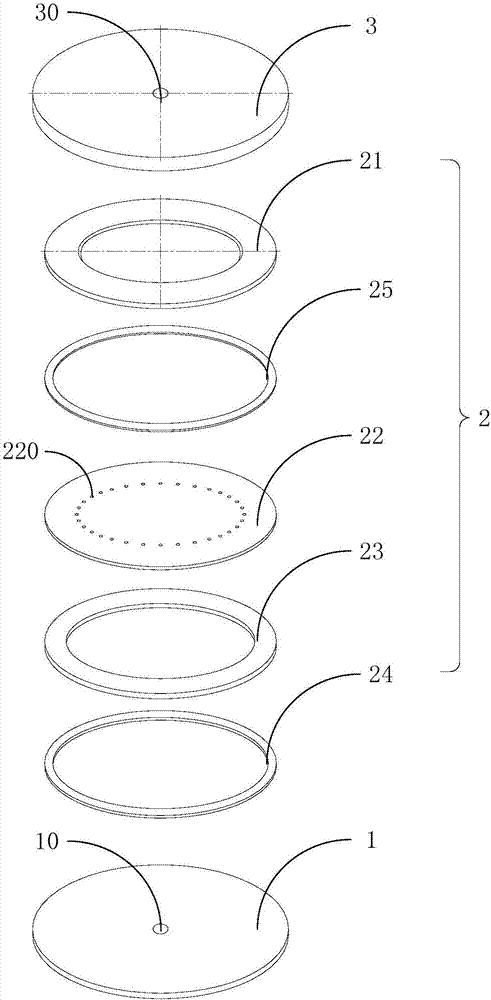
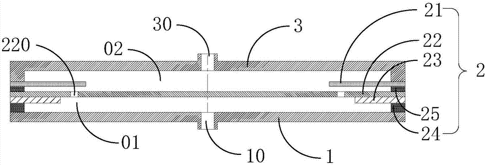
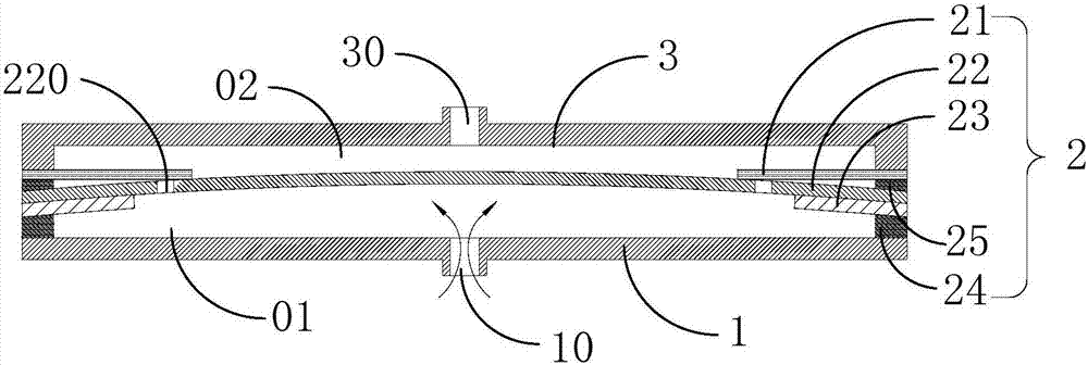
The invention provides a piezoelectric pump and an electronic product, and relates to the technical field of piezoelectric components. The piezoelectric pump comprises a first cover plate, a piezoelectric element and a second cover plate. An air inlet hole is formed in the first cover plate, and an air outlet hole is formed in the second cover plate. The edge of the piezoelectric element is located between the first cover plate and the second cover plate, and fixed by the first cover plate and the second cover plate. The piezoelectric element comprises a piezoelectric vibrator and an annular check sheet, the piezoelectric vibrator comprises a vibration diaphragm and an annular piezoelectric, and the vibration diaphragm is attached to the edge of the annular piezoelectric. Air vents are formed in the vibration diaphragm, the annular piezoelectric is located on one side, facing the first cover plate, of the vibration diaphragm and recedes the air vents, and the annular piezoelectric is used for generating the vibration quantity after being triggered and transmitting the vibration quantity to the vibration diaphragm. The annular check sheets are arranged on one side, close to the second cover plate, of the vibration diaphragm, and cover the positions above the air vents of the vibration diaphragm in an opening and closing mode. The piezoelectric pump is simple in structure, smallin size and low in power consumption, the phenomenon that opening and closing of a valve body is hysteretic does not occur, and the pump output is large.

Description

technical field [0001] The invention relates to the technical field of piezoelectric devices, in particular to a piezoelectric pump and electronic products. Background technique [0002] The piezoelectric pump uses the inverse piezoelectric effect of the piezoelectric ceramic to deform the piezoelectric vibrator (piezoelectric ceramic sheet), and then the volume change of the pump chamber is generated by the deformation to realize the fluid output, or the piezoelectric vibrator generates fluctuations to transmit the fluid, and can The output flow is controlled according to the applied voltage or frequency, which can be widely used in small mobile devices, CPU and display cards, game console control boards, notebook computers and other ancillary products. [0003] As the current consumer electronics products are becoming more and more ultra-thin and miniaturized, but the amount of information to be processed is increasing, so heat dissipation has become an urgent problem to b...

Claims


Application Information

Patent Timeline
IPC IPC(8): F04B43/04
Inventor 施立志丁耀民
Owner SUZHOU PANT PIEZOELECTRIC TECH
Learn More