
Casing processing device for axial flow air compressor based on synthetic jet

A technology of axial flow compressor and synthetic jet, which is applied to parts of pumping devices for elastic fluids, machines/engines, mechanical equipment, etc., can solve the problem of limited application range, synthetic jet technology has not been practically applied, and increased equipment Negative complexity and other issues

Inactive Publication Date: 2018-01-12
NORTHWESTERN POLYTECHNICAL UNIV
View PDF5 Cites 1 Cited by
  • Summary
  • Abstract
  • Description
  • Claims
  • Application Information

AI Technical Summary

Problems solved by technology

At present, great progress has been made in the research and application of synthetic jets in improving airfoil lift, delaying wing stall, enhancing fuel mixing in aero-engine combustors, and controlling separation of turbine cascades. However, in compressors, synthetic jets Jet technology has not been used in practice
The casing treatment is an important means to improve the stability of the compressor. Among them, air injection and suction are the two main casing treatment methods. Although the traditional air injection and suction have achieved certain results in the expansion and stability of the compressor, but Both of these two methods must connect the compressor with the outside world, which increases the complexity of the equipment and greatly limits its application range, so that it eliminates the feasibility of its application on aero-engines

Method used


Image

  • Casing processing device for axial flow air compressor based on synthetic jet
  • Casing processing device for axial flow air compressor based on synthetic jet
  • Casing processing device for axial flow air compressor based on synthetic jet

Examples


Embodiment

[0021] This embodiment is applied on the isolated rotor of a certain axial flow compressor laboratory, and the design parameters of the rotor are as follows:

[0022] Table 1 Design parameters of the rotor

[0023]

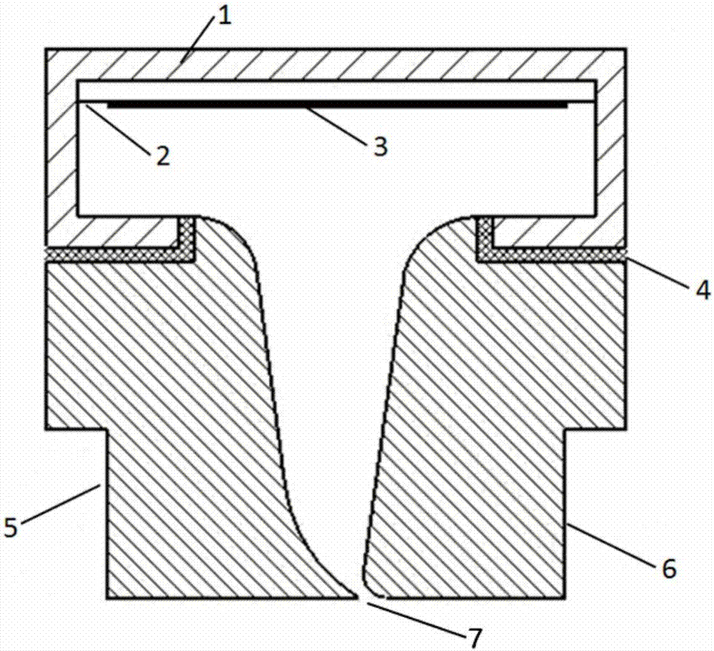
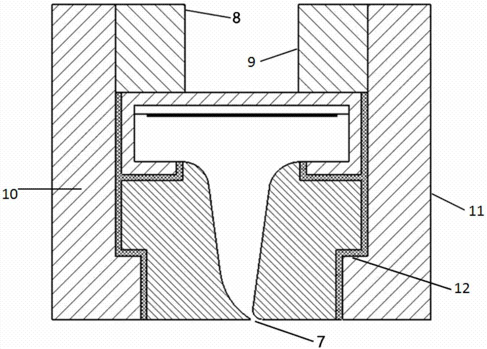
[0024] figure 1 The sectional structure of the synthetic jet generator shown is obtained by rotating 6° along the rotation axis of the impeller. The synthetic jet generator consists of a cavity 1 , a metal film 2 , a piezoelectric layer 3 , a first solid block 5 , and a second solid block 6 . Wherein, the metal film 2 is fixed on the upper part of the cavity 1 , and the metal film 2 is used to install and support the piezoelectric layer 3 . The piezoelectric layer 3 is fixed under the metal film 2 and is opposite to the jet hole 7 formed by the first solid block 5 and the second solid block 6 located at the lower part of the cavity 1, and the first solid block 5 and the second solid block 6 are clamped on the At the groove shoulder 12 on the inner wall of th...


PUM

PropertyMeasurementUnit
Axial dimensionaaaaaaaaaa

Abstract

The invention discloses a casing processing device for an axial flow air compressor based on synthetic jet. The casing processing device is characterized in that a T-shaped groove is formed in a wallsurface of a casing for assembling a synthetic jet generator; the synthetic jet generator is located on an upstream of the front edge of a rotor blade; a flow field is subjected to periodical excitation by the synthetic jet generator, so that energy is injected to the flow field; low-energy fluids in boundary layers around a jet hole can be absorbed through a pumping process of the periodical excitation; kinetic energy of fluids around the jet hole can be improved through a jet process; a vortex structure formed by the periodical excitation spreads to the downstream along with a main flow, sothat mass and momentum exchange between the main flow and low-energy fluids in a separation zone is intensified; the energy of the low-energy zone fluids is increased, and the separation zone is weakened. At a certain synthetic jet frequency, disturbance applied to the flow field by the jet generator is coupled with unsteady disturbance of a blade tip leaking flow, so that unsteadiness of the blade tip leaking flow is weakened. The flowing environment of the rotor blade tip of the air compressor is improved; loss is reduced; and the stable working range of the air compressor is widened.

Description

technical field [0001] The invention relates to the technical field of turbomachinery, in particular to a casing treatment device for an axial flow compressor based on a synthetic jet. Background technique [0002] Synthetic jet is a jet method that combines suction and jet periodically. Based on the theory of vortex motion, synthetic jet technology is increasingly used as a means of flow control. At present, great progress has been made in the research and application of synthetic jets in improving airfoil lift, delaying wing stall, enhancing fuel mixing in aero-engine combustors, and controlling separation of turbine cascades. However, in compressors, synthetic jets Jet technology has not found practical application. The casing treatment is an important means to improve the stability of the compressor. Among them, air injection and suction are the two main casing treatment methods. Although the traditional air injection and suction have achieved certain results in the ex...

Claims


Application Information

Patent Timeline
IPC IPC(8): F04D29/54
Inventor 吴艳辉杨国伟陈智洋安光耀关瑞卿
Owner NORTHWESTERN POLYTECHNICAL UNIV
Learn More