
Laser attenuating device

A laser attenuation and laser technology, applied in lasers, laser parts, optics, etc., can solve the problems of difficult processing of polarizing edge windows and easy generation of ghost images on reflective surfaces, so as to improve uniformity and controllability, easy to process, The effect of the simple structure of the device

Inactive Publication Date: 2018-01-12
INST OF ELECTRONICS CHINESE ACAD OF SCI
View PDF6 Cites 4 Cited by
  • Summary
  • Abstract
  • Description
  • Claims
  • Application Information

AI Technical Summary

Problems solved by technology

[0006] The attenuator based on the principle of polarization can not only achieve attenuation by changing the polarization angle of a pair of linear polarization prism windows, but also use the electro-optic effect to achieve attenuation by delaying the phase of elliptically polarized light. Its advantage is that it can withstand higher energy Laser attenuation, the disadvantage is that high-quality polarized prism windows are difficult to process and reflective surfaces are prone to ghost images

Method used

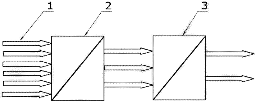
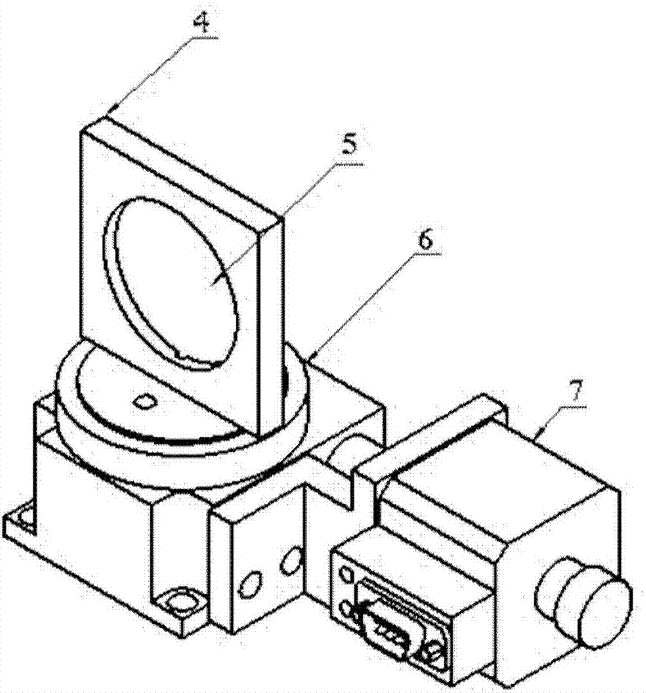
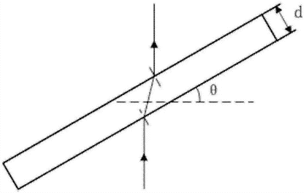

Image

  • Laser attenuating device
  • Laser attenuating device
  • Laser attenuating device

Examples


Embodiment Construction

[0032] In order to make the purpose, technical solutions and advantages of the present disclosure clearer, the present disclosure will be further described in detail below in conjunction with specific embodiments and with reference to the accompanying drawings.

[0033] It should be noted that, in the drawings or descriptions of the specification, similar or identical parts all use the same figure numbers. Implementations not shown or described in the accompanying drawings are forms known to those of ordinary skill in the art. Additionally, while illustrations of parameters including particular values ​​may be provided herein, it should be understood that the parameters need not be exactly equal to the corresponding values, but rather may approximate the corresponding values ​​within acceptable error margins or design constraints. The directional terms mentioned in the embodiments, such as "upper", "lower", "front", "rear", "left", "right", etc., are only referring to the dire...


PUM


Abstract

The invention provides a laser attenuating device. The laser attenuating device comprises a diaphragm and an angle adjusting module, wherein the diaphragm comprises two polishing planes in parallel with each other; the angle adjusting module is used for rotating the diaphragm, so that the angle between a normal of the polishing planes of the diaphragm and an incident laser is adjusted. According to the laser attenuating device, through precise control over the angle between the incident laser and the normal of the two parallel polishing planes of the diaphragm, continuous precise attenuation of the laser intensity is achieved, the uniformity and controllability of attenuation of the laser intensity are improved, and the device is simple in structure and easy to produce.

Description

technical field [0001] The present disclosure relates to the field of optical devices, in particular to a laser attenuation device. Background technique [0002] Laser has the characteristics of good coherence, strong directionality and high brightness, but in the field of laser detection, the intensity of laser signal can easily exceed the response range of the detector, which will saturate or even damage the detector. In order to effectively measure the energy, power, repetition frequency, time distribution and other parameters of the laser, it is often necessary to add an attenuator between the laser signal and the detector to attenuate the intensity of the laser signal to meet the response range of the detector and avoid damage. [0003] At present, there are mainly two types of laser attenuators: one is the attenuator whose thickness of the coating layer changes gradually along a straight line or a circle based on the principle of reflection. Area. The other is an at...

Claims


Application Information

Patent Timeline
Patent Type & Authority Applications(China)
IPC IPC(8): H01S3/10G02B26/08
Inventor 郑义军谭荣清马芳朱子任钟艳红孙科黄文武
Owner INST OF ELECTRONICS CHINESE ACAD OF SCI
Learn More