Low NOX combustion system for travelling grate pelletizing plants

A technology of burners and combustion chambers, applied in the direction of burners, combustion chambers, combustion methods, etc., can solve the problem of increasing the amount of cold primary air

Active Publication Date: 2018-01-12
METSO OUTOTEC (FINLAND) OY
View PDF9 Cites 0 Cited by
  • Summary
  • Abstract
  • Description
  • Claims
  • Application Information

AI Technical Summary

Problems solved by technology

As a result, the main problem with standard burners and combustion methods is that the high flame temperature caused by igniting the undiluted fuel results in a hot flame in the combustion zone wi

Method used


Image

  • Low NOX combustion system for travelling grate pelletizing plants
  • Low NOX combustion system for travelling grate pelletizing plants
  • Low NOX combustion system for travelling grate pelletizing plants

Examples


Embodiment Construction

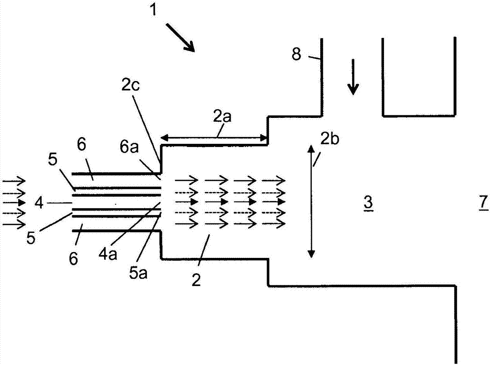
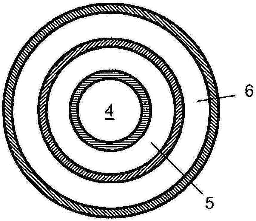
[0041] exist figure 1 In , a burner assembly 1 according to a preferred embodiment of the present invention is shown in cross-section. The burner assembly 1 has a front chamber 2 , a combustion chamber 3 and a fuel inlet pipe 4 , a primary air inlet pipe 5 and a preheated air inlet pipe 6 . These inlet ducts respectively comprise respective fuel inlets 4a, primary air inlets 5a and preheated air inlets 6a.

[0042] A combustion chamber 3 is arranged adjacent to and downstream of the antechamber 2 , the combustion chamber itself being connected to a furnace 7 downstream of the combustion chamber 2 . Furthermore, a combustion air inlet, ie a downcomer 8 , is provided as an inlet to the combustion chamber 3 for introducing combustion air. The vestibule itself has a vestibule length 2a and a vestibule diameter 2b, wherein the length 2a is greater than the diameter 2b. Therefore, the antechamber of the present invention is expected to be smaller than a standard pre-chamber.

[...


PUM


Abstract

The above mentioned invention describes a method for combustion of gaseous or liquid fuel using a burner assembly (1). Therein fuel, cold primary air and preheated air are supplied to a pre-chamber (2), whereby the fuel and cold primary air being supplied through at least one fuel feed (4) and at least one primary air feed (5), and preheated combustion air is supplied to a combustion chamber (3).The preheated air and/or the cold primary air are injected parallel to the fuel into the pre-chamber (2).

Description

technical field [0001] The present invention relates to a method of burning a gaseous fuel or a liquid fuel using a burner assembly, supplying fuel, cold primary air and preheated air to an antechamber, wherein the fuel is supplied by at least one fuel supply and at least one primary air supply and Primary air, which supplies preheated combustion air to the combustion chamber. The invention also relates to burner assemblies for burning gaseous or liquid fuels to heat industrial furnaces. Background technique [0002] Standard burners are often used in burner assemblies such as curing ovens for mobile grate pelletizing equipment. Commonly used burners stabilize the flame just at the burner nozzle end. Due to the high combustion air temperature, typically up to 1000°C, the flame inside the combustion chamber is very hot. Such hot flames with peak temperatures typically as high as 2000° C. lead to very high nitrogen oxide emissions and may also lead to thermal damage at the ...

Claims


Application Information

Patent Timeline
IPC IPC(8): F23C6/04F23D14/22F23D14/66F23D99/00F23L15/00
CPCF23C6/04F23C2900/99001F23D14/22F23D14/66F23D91/02F23L15/00Y02E20/34
Inventor A·穆恩科H·科勒R·马杜塔
Owner METSO OUTOTEC (FINLAND) OY
Why Eureka
Try Eureka