Punching device for electrical equipment manufacturing

A punching device and technology for electrical equipment, applied in the electrical field, can solve problems such as the bottom of punching efficiency, and achieve the effects of improving efficiency, saving processing time, and simplifying punching steps

Inactive Publication Date: 2018-01-16
合肥慕智信息技术有限公司
View PDF6 Cites 12 Cited by
  • Summary
  • Abstract
  • Description
  • Claims
  • Application Information

AI Technical Summary

Problems solved by technology

[0004] Aiming at the deficiencies of the prior art, the present invention provides a punching device for electrical equipment manufacturing, which solves the problem of low punching efficiency

Method used


Image

  • Punching device for electrical equipment manufacturing
  • Punching device for electrical equipment manufacturing

Examples


Embodiment Construction

[0020] The following will clearly and completely describe the technical solutions in the embodiments of the present invention with reference to the accompanying drawings in the embodiments of the present invention. Obviously, the described embodiments are only some, not all, embodiments of the present invention. Based on the embodiments of the present invention, all other embodiments obtained by persons of ordinary skill in the art without making creative efforts belong to the protection scope of the present invention.

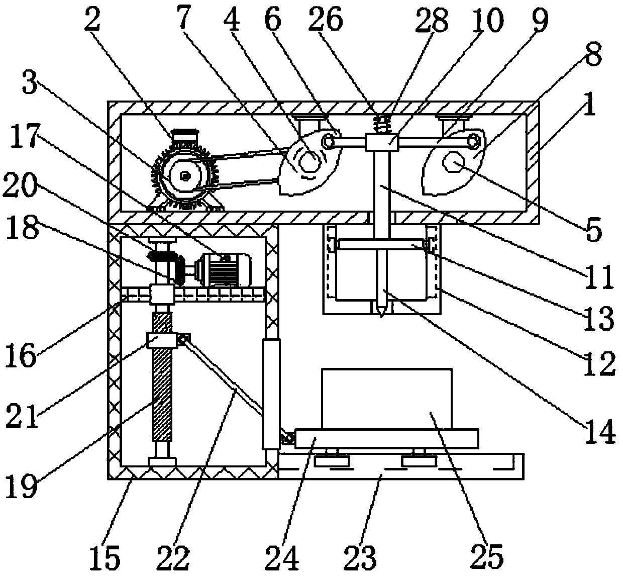
[0021] see Figure 1-2 , the present invention provides a technical solution: a punching device for electrical equipment manufacturing, including a top box 1, a first motor 2 is fixedly connected to the left side of the inner wall of the top box 1, and the surface of the output shaft of the first motor 2 is sleeved There is a first pulley 3, the top of the inner wall of the top box 1 is fixedly connected with the first rotating shaft 4 and the second rotating ...


PUM


Abstract

The invention discloses a punching device for electrical equipment manufacturing, and relates to the technical field of electrical equipment. The punching device comprises a top box, a first motor isfixedly connected to the left side of the inner wall of the top box, the surface of a first motor output shaft is sleeved with a first belt pulley, a first rotary shaft and a second rotary shaft are fixedly connected to the top of the inner wall of the top box from left to right in sequence through link rods, a first cam and a second belt pulley are rotatably connected to the surface of the firstrotary shaft from front to back in sequence, the surface of the second belt pulley is in drive connection with the first belt pulley through a belt, the second cam is rotatably connected to the surface of the second rotary shaft, and a connecting rod is rotatably connected to the front of the second cam through the link rod. The punching device for electrical equipment manufacturing achieves the purpose of punching an electrical equipment shell, also drastically simplifies the steps of punching, improves the punching efficiency, therefore improves the overall efficiency of electrical equipmentmachining and saves the machining time of the electrical equipment.

Description

technical field [0001] The invention relates to the field of electrical technology, in particular to a punching device for manufacturing electrical equipment. Background technique [0002] Electrical equipment is a general term for generators, transformers, power lines, circuit breakers and other equipment in the power system. The important role played by electricity in our life and production cannot be ignored. It brings us great convenience and becomes our The production of important energy in life, the most critical factor in the power plant to allow the normal operation and transmission of electricity is electrical equipment. [0003] For holes on electrical equipment, the traditional method is to drill holes on a machine tool or use a hydraulic rod to punch holes. Although the accuracy and effect are good, the cost is relatively high, and special equipment is required for drilling. Drill bits, drilling machines, etc. are cumbersome to operate. In addition, when hydraul...

Claims


Application Information

Patent Timeline
Patent Type & Authority Applications(China)
IPC IPC(8): B21D28/24B26F1/24B26D5/16
Inventor 杨延玲
Owner 合肥慕智信息技术有限公司
Why Eureka
Try Eureka