Eureka AIR delivers breakthrough ideas for toughest innovation challenges, trusted by R&D personnel around the world.

Spring machining and deburring treatment device

A processing device and deburring technology, which is applied in metal processing equipment, manufacturing tools, grinding workpiece supports, etc., can solve problems that affect the appearance of springs and the accuracy of installation, burrs on the outer surface of springs, and hand injuries of operators. Achieve the effect of improving grinding precision, improving grinding efficiency and improving grinding uniformity

Pending Publication Date: 2018-01-16
NANJING LISHUI LIHUA SPRING FACTORY
View PDF0 Cites 3 Cited by
  • Summary
  • Abstract
  • Description
  • Claims
  • Application Information

AI Technical Summary

Problems solved by technology

[0002] A spring is a mechanical part that uses elasticity to work. Parts made of elastic materials are deformed under the action of external force, and then return to their original shape after removing the external force. When the spring leaves the factory, because the surface of the spring itself is not smooth or the spring is bent The unevenness of the folding tool will cause burrs on the outer surface of the spring. The burrs not only affect the appearance of the spring and the accuracy of installation, but also cause damage to the hands of the operator during the installation process. Secondly, the existing spring grinding and deburring equipment fixture Usually designed for a specific size spring, the compatibility is poor, so we propose a spring processing deburring device

Method used


Image

  • Spring machining and deburring treatment device
  • Spring machining and deburring treatment device
  • Spring machining and deburring treatment device

Examples


Embodiment Construction

[0018] In order to make the technical means, creative features, objectives and effects achieved by the present invention easy to understand, the present invention will be further explained below in conjunction with specific embodiments.

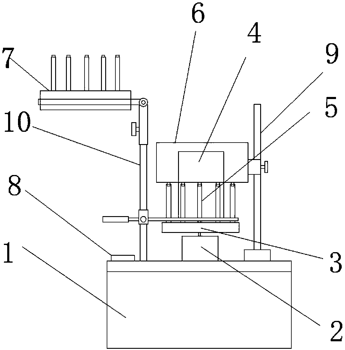
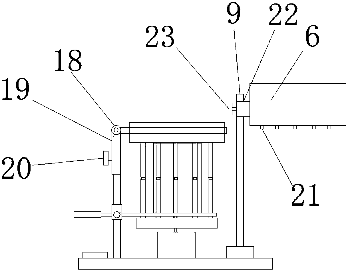
[0019] Such as Figure 1-3 As shown, a spring processing and deburring treatment device includes a base 1, a driving device 2, a disc grinding base 3, a cylindrical grinding sheet 4, a vertical rod 5, an upper cover 6, a secondary disc grinding base 7 and a control panel 8. The upper middle of the base 1 is provided with a driving device 2, the upper end of the driving device 2 is provided with a disc grinding base 3, the upper end of the disc grinding base 3 is provided with a vertical rod 5 on the outer wall, and the upper end of the disc grinding base 3 A cylindrical polishing sheet 4 is provided in the middle. The lower end of the cylindrical polishing sheet 4 is placed on the shaft of the driving device 2, and the upper end of the cylindric...


PUM


Abstract

The invention discloses a spring machining and deburring treatment device which comprises a base, a driving device, a disc grinding base, a cylindrical grinding piece, vertical rods, an upper cover, asecondary disc grinding base and a control panel. The driving device is arranged in the middle of the upper end of the base, the disc grinding base is arranged at the upper end of the driving device,the vertical rods are arranged on the outer wall of the upper end of the disc grinding base, the cylindrical grinding piece is arranged in the middle of the upper end of the disc grinding base, the lower end of the cylindrical grinding piece is arranged on a driving device rotary shaft, the upper cover is arranged at the upper end of the cylindrical grinding piece, the right end of the upper cover is connected with the base through a supporting rod a, a supporting rod b is arranged on the left side of the upper end of the base, the control panel is arranged at the left end of the supporting rod b, and the secondary disc grinding base is arranged at the upper end of the supporting rod b. The spring machining and deburring treatment device can simultaneously conduct omnibearing grinding onmultiple springs by arranging multiple vertical rods and the cylindrical grinding piece at the upper end of the disc grinding base, is conductive to improvement of the grinding efficiency and is morepractical and suitable for wide popularization and use.

Description

Technical field [0001] The invention relates to a spring processing equipment, in particular to a spring processing deburring processing device. Background technique [0002] A spring is a mechanical part that uses elasticity to work. A part made of elastic material deforms under the action of external force, and returns to its original shape after removing the external force. When the spring leaves the factory, the surface of the spring itself is not smooth or the spring is bent. The unevenness of the folding tool will cause burrs on the outer surface of the spring. The burrs not only affect the appearance of the spring and the accuracy of installation, but also cause damage to the operator's hands during the installation process. Secondly, the existing spring polishing and deburring equipment fixture It is usually designed for springs of specific sizes and has poor compatibility. Therefore, we propose a spring processing deburring device. Summary of the invention [0003] The m...

Claims


Application Information

Patent Timeline
IPC IPC(8): B24B9/04B24B41/06
Inventor 李益强
Owner NANJING LISHUI LIHUA SPRING FACTORY
Why Eureka
Eureka Blog
Learn More