Automotive brake pad production line

A technology for brake pads and production lines, applied to other manufacturing equipment/tools, manufacturing tools, etc., can solve problems such as poor fixation of the bottom of the equipment, easy deviation of drilling positions, uneven heat treatment, etc., to improve tablet pressing accuracy and processing efficiency And product quality, improve the uniformity of heat treatment, improve the effect of printing accuracy

Active Publication Date: 2015-04-01
HUANGSHAN FEIYING AUTO PARTS
View PDF5 Cites 17 Cited by
  • Summary
  • Abstract
  • Description
  • Claims
  • Application Information

AI Technical Summary

Problems solved by technology

[0003] The tablet pressing device mainly has defects such as complex structure, high cost, inability to achieve good clamping and adjustment of the die of the tablet press, which leads to easy deviation of the tablet pressing position, and low product quality.
[0004] The heat treatment device mainly has defects such as uneven heat treatment and uneven product quality. The main reason is that the automobile brake pads cannot conduct heat evenly.
In addition, the existing heat treatment device needs manual unloading and handling after the processing is completed, and the processing efficiency is low
[0005] The grinding device mainly has defects such as complex structure, high cost, inability to move or adjust the brake pad clamp, which leads to easy deviation of the grinding position, etc.
[0006] The drilling device mainly has defects such as complex structure, high cost, inability to position the automobile brake pad fixture, and inability to adjust the fixture well, which leads to deviations in the drilling position, which greatly affects the product quality.
[0007] The coding device mainly has defects such as complex structure, high cost, and poor fixation at the bottom of the equipment, which leads to the inability to adjust the coding position and the prone deviation of the coding position.

Method used


Image

  • Automotive brake pad production line
  • Automotive brake pad production line
  • Automotive brake pad production line

Examples


Embodiment Construction

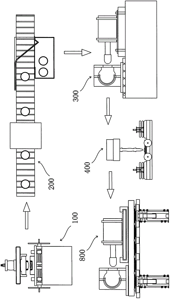
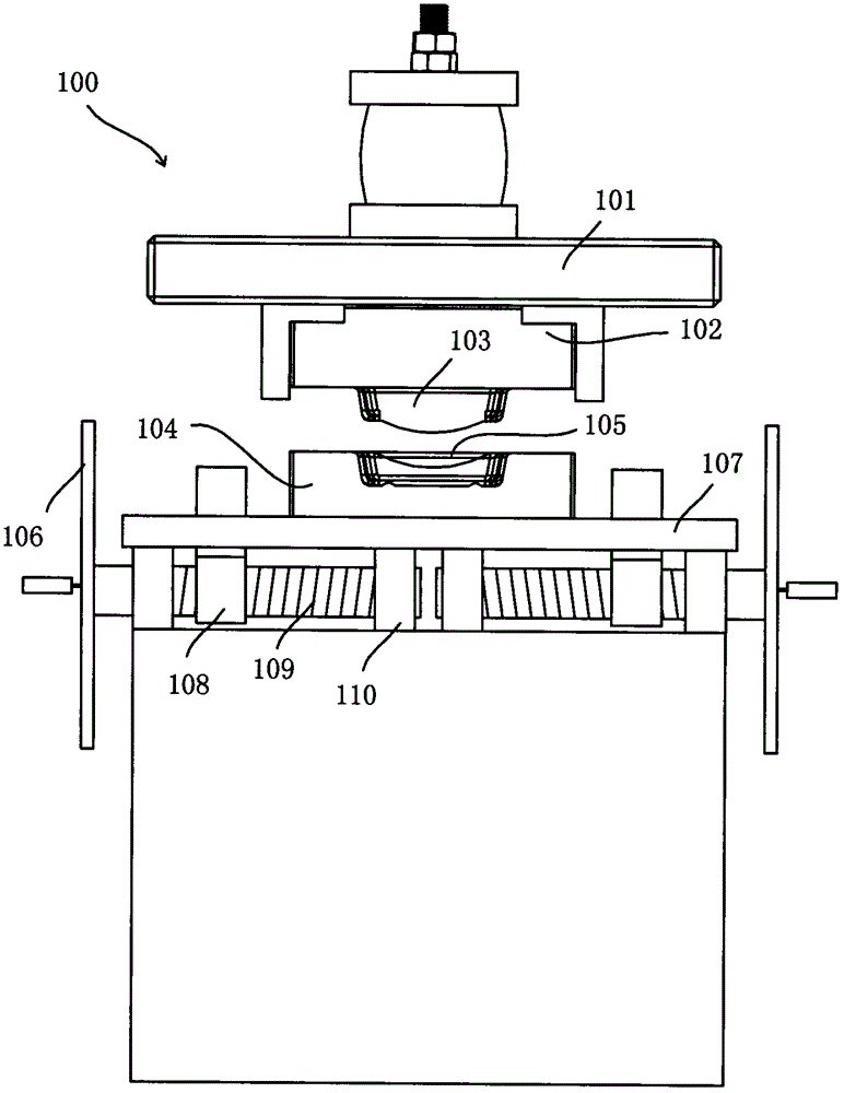
[0032] In order to further describe the present invention, the present invention will be further described in detail below in conjunction with the accompanying drawings and embodiments. Figure 1-11 The automobile brake pad production line shown includes a tablet pressing device 100, a heat treatment device 200, a grinding device 300, a drilling device 400, a coding device 800, and a conveying device connecting each device.

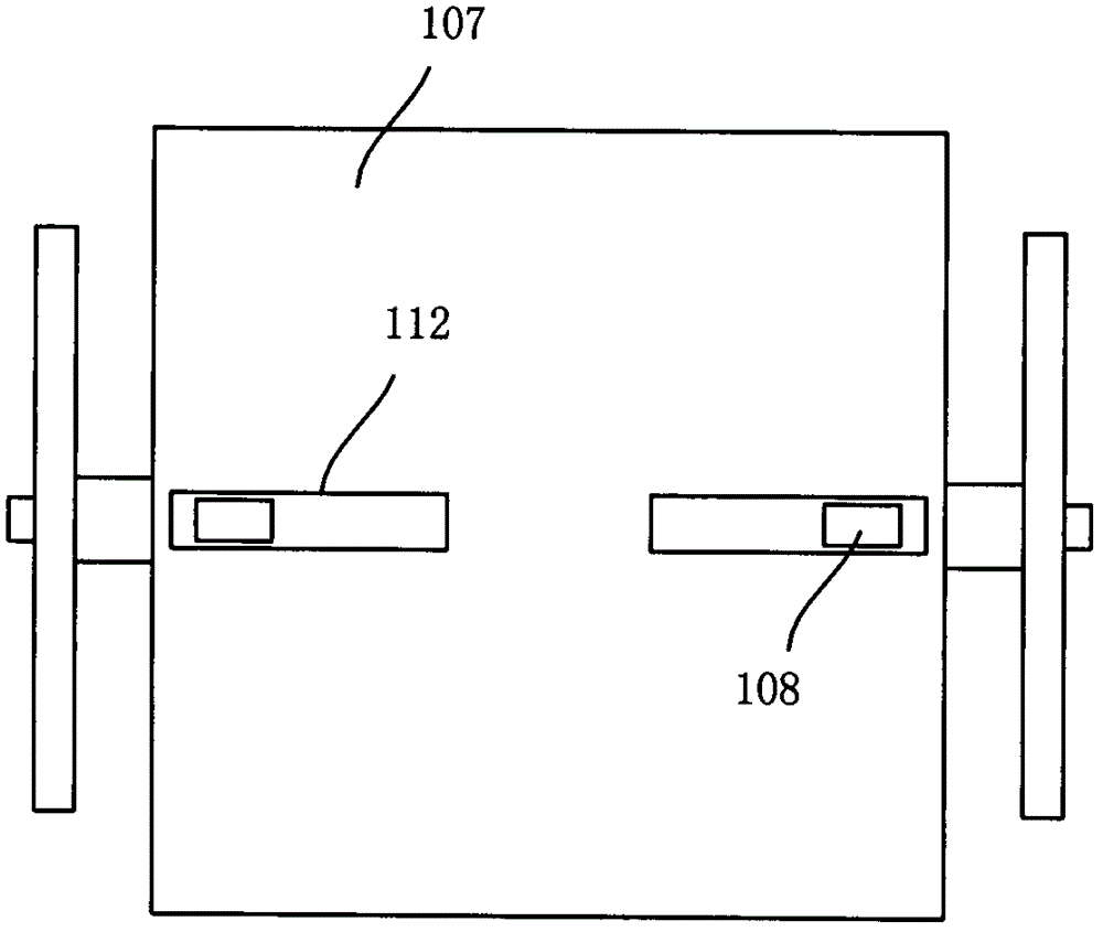
[0033]The tablet pressing device 100 includes an upper die 102 and a lower die 104 , the bottom of the upper die 102 is provided with a brake pad pressing punch 103 , and the upper part of the upper die 102 is provided with a top plate 101 and a hydraulic press placed on top of the top plate 101 . The lower mold 104 is provided with a brake pad pressing die 105 matched with the brake pad pressing punch 103, the lower die 104 is placed in the die clamping fixture, and the die clamping fixture includes a square fixing plate 107, The fixing plate 107 is prov...


PUM


Abstract

The invention relates to an automotive brake pad production line which comprises a tabletting device, a thermal treatment device, a grinding device, a drilling device, a code spraying device and a conveying device connected among the former. Through the tabletting device, a concave die can be closely clamped, so that position of the concave die can be adjusted accurately; through the thermal treatment device, an automotive brake pad storage shelf after being subjected to thermal treatment can be automatically conveyed to a goods storage area, and heat transfer efficiency of a drum brake pad is improved; through the grinding device, an automotive brake pad is closely clamped, and position of an automotive brake pad clamp can be adjusted accurately, so that grinding accuracy is improved remarkably; through the drilling device, the automotive brake pad is closely clamped, the position of the automotive brake pad can be adjusted accurately, and a clamping clamp can be accurately positioned, so that drilling accuracy is improved remarkably; through the code spraying device, the brake pad is clamped closely, code spraying accuracy is improved, and one-step code spraying forming of multiple batches of brake pads is realized.

Description

technical field [0001] The invention relates to an automobile brake pad production line. Background technique [0002] In the field of automobile brake pad processing, the existing production lines mainly have the following defects: [0003] The tablet pressing device mainly has defects such as complex structure, high cost, inability to achieve good clamping and adjustment of the die of the tablet press, which leads to easy deviation of the tablet pressing position, and low product quality. [0004] The heat treatment device mainly has defects such as uneven heat treatment leading to uneven product quality. The main reason is that the automobile brake pads cannot conduct heat evenly. In addition, the existing heat treatment device needs manual unloading and handling after the processing is completed, and the processing efficiency is low. [0005] The grinding device mainly has defects such as complex structure, high manufacturing cost, inability to move or adjust the brake...

Claims


Application Information

Patent Timeline
Patent Type & Authority Applications(China)
IPC IPC(8): B23P23/06
CPCB23P23/06
Inventor 章志华杜孟子
Owner HUANGSHAN FEIYING AUTO PARTS
Why Eureka
Try Eureka