Bridge type numerical control planogrinder structure

A gantry grinding machine and bridge type technology, which is applied in grinding machines, grinding/polishing equipment, metal processing equipment, etc., can solve the problem that it is difficult to meet the requirements of large workpiece processing, the processing accuracy of processed parts is reduced, and general products do not have suitable structures. and other problems, to achieve the effect of improving rapid traverse speed and stability, improving bearing capacity, improving processing accuracy and work efficiency

Inactive Publication Date: 2012-08-01
深圳市盛德丰精密机床有限公司
View PDF9 Cites 17 Cited by
  • Summary
  • Abstract
  • Description
  • Claims
  • Application Information

AI Technical Summary

Problems solved by technology

Therefore, there are problems such as large friction force, low load capacity of the workbench, large thrust force required, poor force effect, unstable fast moving speed, and high impact force.
These problems will cause processing errors, reduce the processing accuracy of the processed parts, and affect the working efficiency of the grinding machine.
At the same time, due to the large weight limit of conventional grinding machines for processing large workpieces, it is difficult to meet the requirements of modern manufacturing for processing large workpieces
[0003] This shows that above-mentioned existing conventional grinding machine obviously still has inconvenience and defect in structure and use, and urgently needs to be further improved
In order to solve the above-mentioned problems, the relevant manufacturers have tried their best to find a solution, but for a long time no suitable design has been developed, and the general product has no suitable structure to solve the above-mentioned problems. This is obviously the relevant industry. Urgent problem

Method used


Image

  • Bridge type numerical control planogrinder structure
  • Bridge type numerical control planogrinder structure
  • Bridge type numerical control planogrinder structure

Examples


Embodiment Construction

[0033] In order to further explain the technical means and effects that the present invention takes to achieve the intended purpose of the invention, below in conjunction with the accompanying drawings and preferred embodiments, the specific implementation, structure, features and details of the bridge-type CNC gantry grinding machine structure proposed according to the present invention will be described below. Its effect is described in detail below.

[0034] The aforementioned and other technical contents, features and effects of the present invention will be clearly presented in the following detailed description of preferred embodiments with reference to the drawings. For convenience of description, in the following embodiments, the same elements are denoted by the same numbers.

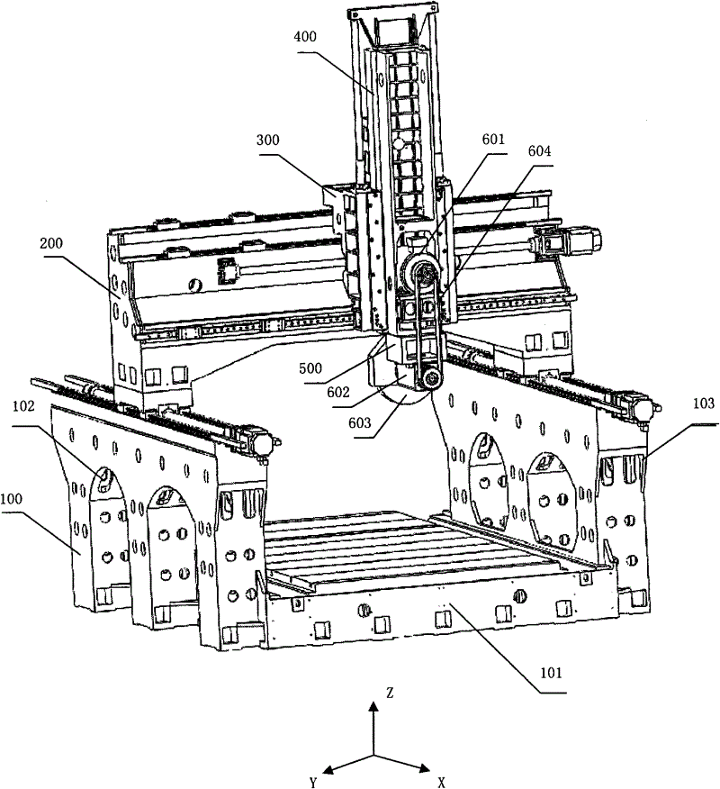
[0035] see figure 1 Shown is a schematic diagram of the structure of the bridge type CNC gantry grinder in a preferred embodiment of the present invention. The structure of the bridge type CNC...


PUM


Abstract

The invention relates to a bridge type numerical control planogrinder structure, which comprises a base, a beam, a sliding saddle, a ram, a grinding head box body and a dynamic-static grinding head assembly, wherein a workbench is arranged in the base, the beam is arranged on the base, the sliding saddle is arranged on the beam in sliding mode, and a guide rail and a lead screw pair are arranged in the direction that the sliding saddle is perpendicular to the workbench. The ram is arranged on the sliding saddle and in sliding connection with the guide rail of the sliding saddle in mutual matching mode. The grinding head box body is fixedly arranged at the lower end of the ram, and the dynamic-static grinding head assembly is arranged on the grinding head box body. The dynamic-static grinding head assembly comprises a grinding head motor, a dynamic-static grinding head spindle, a grinding wheel and a multi-wedge pulley, wherein the grinding wheel is arranged at one end of the dynamic-static grinding head spindle, the dynamic-static grinding head spindle is arranged below the grinding head box body, the grinding head motor is arranged in the ram, and the multi-wedge pulley is connected an output shaft of the grinding head motor and the other end of the dynamic-static grinding head spindle. Therefore, the bridge type numerical control planogrinder structure is simple and convenient to process, reliable in work and capable of improving processing precision and working efficiency.

Description

technical field [0001] The invention relates to a numerical control processing machine, in particular to a bridge type numerical control gantry grinder structure. Background technique [0002] At present, conventional grinding machines all adopt the movable worktable, and the worktable is moved by the push and pull of the oil cylinder, and the guide rail of the worktable adopts V-flat or double-V guide rails. Therefore, there are problems such as large friction force, low load capacity of the workbench, large thrust force required, poor force bearing effect, unstable fast moving speed, and high impact force. These problems will cause processing errors, reduce the processing accuracy of the processed parts, and affect the working efficiency of the grinding machine. At the same time, due to the large weight limit of conventional grinding machines for processing large workpieces, it is difficult to meet the requirements of modern manufacturing for processing large workpieces. ...

Claims


Application Information

Patent Timeline
Patent Type & Authority Applications(China)
IPC IPC(8): B24B27/00
Inventor 张春林梁东屹
Owner 深圳市盛德丰精密机床有限公司
Why Eureka
Try Eureka