
Emergency braking device with auxiliary braking function for vehicle

An emergency braking and auxiliary braking technology, applied in the direction of brakes, braking components, vehicle components, etc., can solve the problems of brake failure, inertia rollover, vehicle instability, etc., to reduce the probability of locking and improve stability. Safety and security, the effect of improving the heat dissipation speed

Pending Publication Date: 2018-01-16
CHANGZHOU VOCATIONAL INST OF ENG
View PDF0 Cites 0 Cited by
  • Summary
  • Abstract
  • Description
  • Claims
  • Application Information

AI Technical Summary

Problems solved by technology

To sum up, the more effective braking methods in the driving process are the service brake, the second brake and the auxiliary brake, but there are also the following problems: (1) on the service brake, the conventional disc Braking is easy to cause a locked state due to emergency braking, especially in the case of high-speed operation, emergency braking will easily cause a high pressure difference and fit between the brake pad and the brake disc, making it impossible to separate again, causing the vehicle to fail. If the disc brake effect is weakened, the brake will not work; (2) In the process of emergency braking, the most likely problem is inertia rollover, and most of them Some of them are inertial forward rollover and rollover; the current second braking device is rarely equipped with related devices to suppress this situation; (4) the current conventional auxiliary braking does not completely combine other types of braking devices to Enhance the vehicle's grip performance to improve the stability of the vehicle's center of gravity and reduce the wear and tear of other braking devices

Method used


Image

  • Emergency braking device with auxiliary braking function for vehicle
  • Emergency braking device with auxiliary braking function for vehicle
  • Emergency braking device with auxiliary braking function for vehicle

Examples


Embodiment

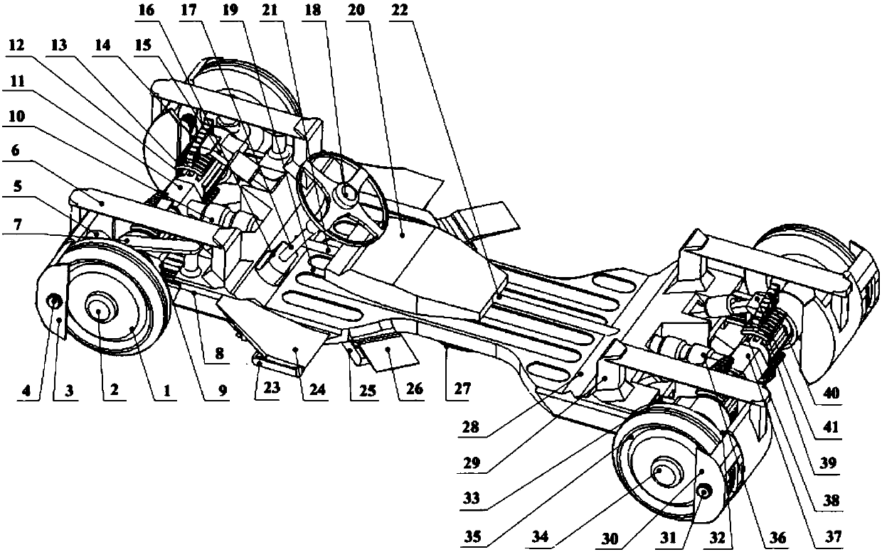
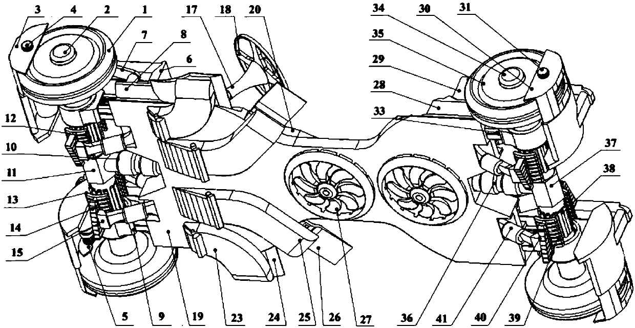
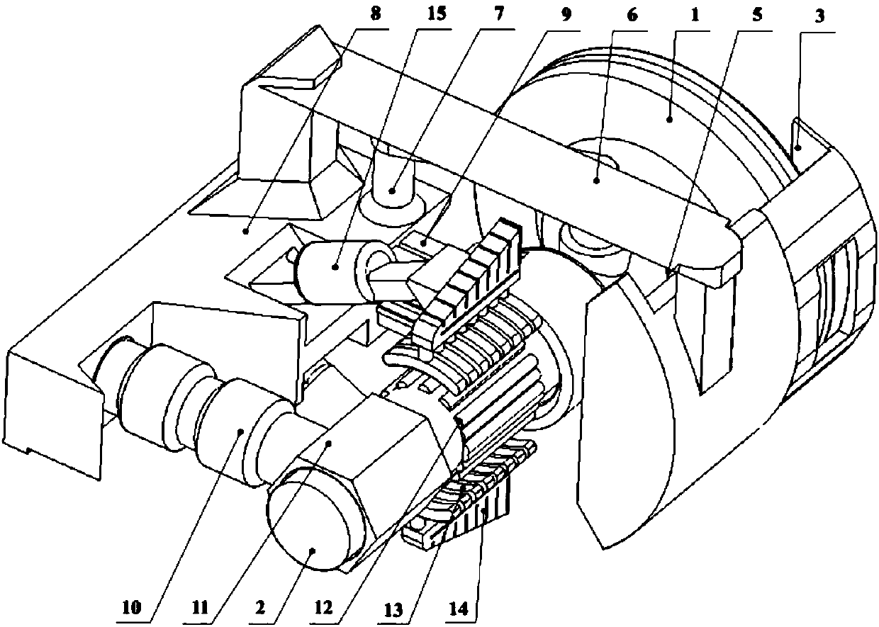
[0045] combine figure 1 and figure 2 Shown, a kind of vehicle braking device of present embodiment, its vehicle chassis comprises front wheel 1, front axle 2, bogie 7, front console 8, front bushing 9, front drive shaft 10, front drive bushing 11 , torque table 16, transmission rod 17, steering wheel 18, chassis plate 19, engine block 20, front drive sensing shaft 21, rear drive sensing shaft 22, rear console 28, rear bushing 33, rear axle 34, rear Wheel 35, rear drive shaft 36 and rear drive shaft sleeve 37, front wheel 1 is nested in front axle 2 two ends, front axle sleeve 9 one ends and front axle 2 are nested, and the other end is arranged on front console 8 front end both sides ( see Figure 6 shown); bogie 7 one end is arranged on the front axle 2, and the other end is arranged on the front console 8, and one end of the front drive shaft 10 is connected with the front drive bushing 11, and the other end is arranged at the front center of the front console 8, The fro...


PUM


Abstract

The invention discloses an emergency braking device with an auxiliary braking function for a vehicle and belongs to the field of vehicle braking. The emergency braking device with the auxiliary braking function for the vehicle comprises emergency braking mechanisms arranged at front wheels and rear wheels of the vehicle and an auxiliary braking mechanism arranged at the bottom of the vehicle, wherein the emergency braking mechanisms comprise braking plates, outer side braking buckles, inner side braking pads and supporting wings; each outer braking buckle is nested in one side of the corresponding braking plate and positioned at the outer side of the corresponding front wheel and the corresponding rear wheel; each inner braking pad is arranged at the other side of the corresponding brakingplate and positioned at the inner side of the corresponding front wheel and the corresponding rear wheel; and the auxiliary braking mechanism comprises vortex fans arranged at the bottom of a chassisof the vehicle. Under the premise of not weakening the braking effect, the emergency braking device with the auxiliary braking function for the vehicle greatly reduces the probability of locking states during the emergency braking, so that the vehicle are not liable to instability caused by locking and can be steered during the emergency braking. At the same time, the use of the auxiliary brakingmechanism effectively restrains the vehicle from overturning caused by inertia and improves the adaptability to different road conditions of the vehicle.

Description

technical field [0001] The invention relates to a vehicle braking device, more specifically, to a vehicle emergency braking device with auxiliary braking function. Background technique [0002] With the improvement of my country's economic level, the number of private vehicles in my country has grown rapidly and has become the first in the world, and the total production of vehicles in my country is also the first in the world. Safety performance is the most critical indicator of vehicle performance, and braking performance is the key among the keys. In the conventional definition, the braking system is a series of special devices used on the vehicle to make the outside world (mainly the road surface) exert a certain force on some parts of the car (mainly the wheels), so as to perform a certain degree of forced braking on it. Conventional brake devices include engine brake, parking brake, service brake, secondary brake and auxiliary brake. Among them, engine braking refers...

Claims


Application Information

Patent Timeline
Patent Type & Authority Applications(China)
IPC IPC(8): B60T1/12B60T1/06B60T1/16
Inventor 王中磊王鑫铝李锐马国新何元福
Owner CHANGZHOU VOCATIONAL INST OF ENG
Learn More